

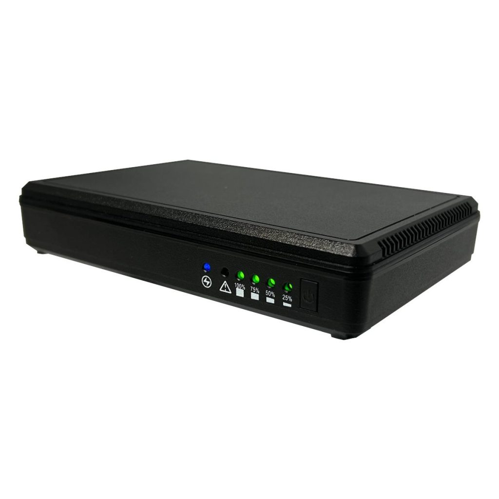
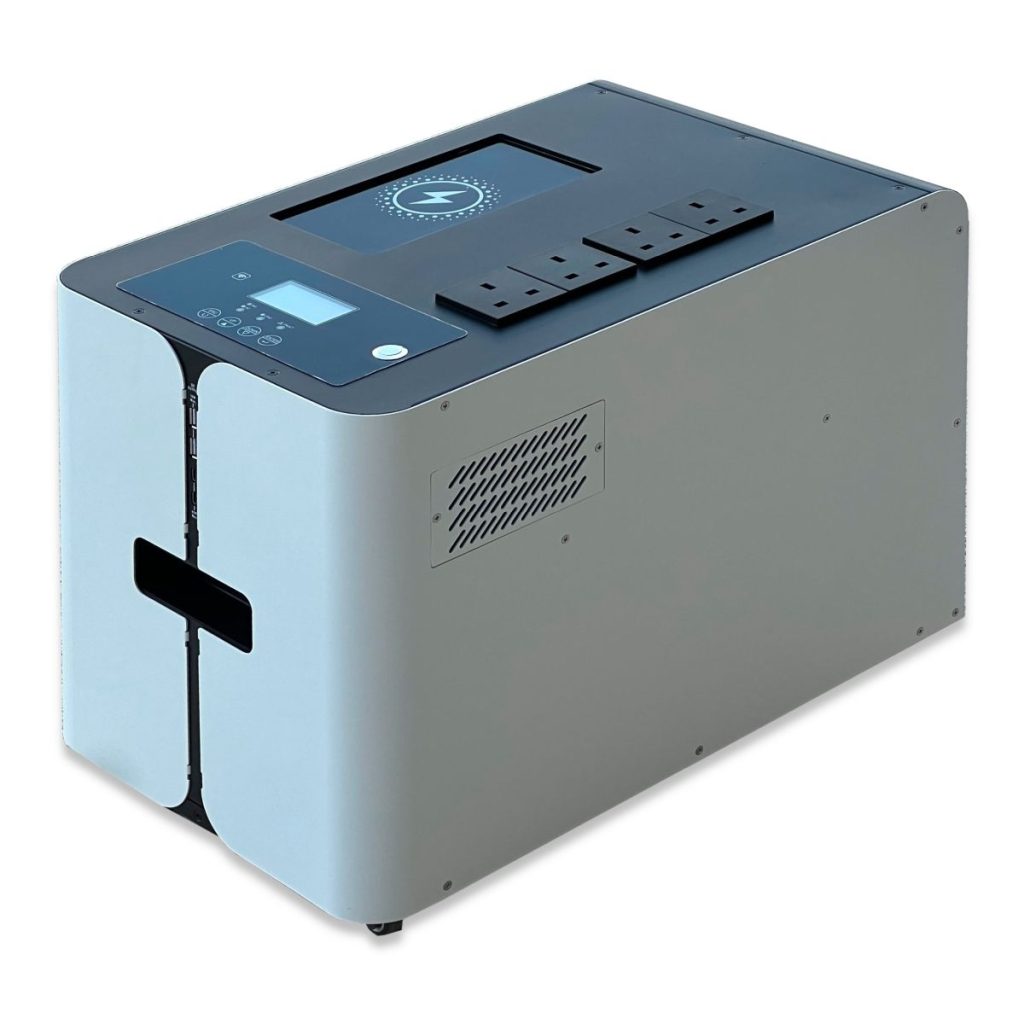
The Power Inspired Gateway is a product designed specifically for door access applications, where rather than needing Uninterrupted Power, you need on demand AC power for door motors. However, due to start up currents larger motors may exceed the 1200W rating of the Gateway. At this point a higher powered system is required, which is where the Power Inspired VFI Online UPS for door applications can be used. In addition, the square wave nature of the GW-SX units may not be compatible and a sine wave unit would be preferable.
Although the VFI range offers very high degrees of power protection considered overkill for door access applications, they have programmable features that make it very suitable. For example:
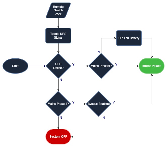
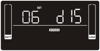
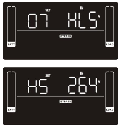
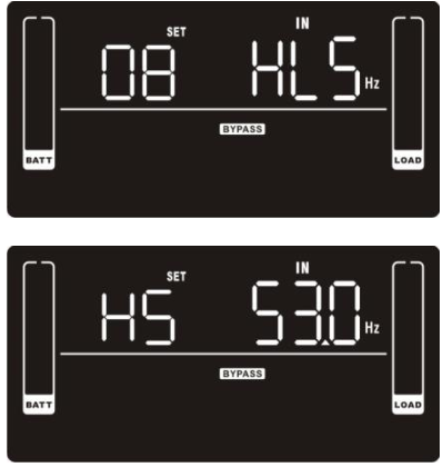
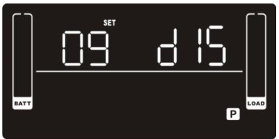
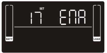
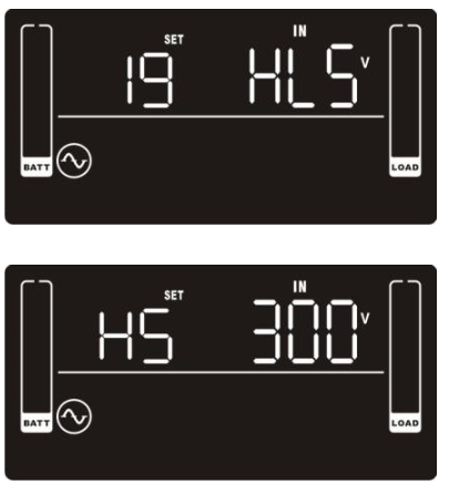
- Bypass. You can set the system to have bypass enabled. This means that if the UPS is in standby or has developed a fault, as long as mains power is available there will be power at the output of the UPS.
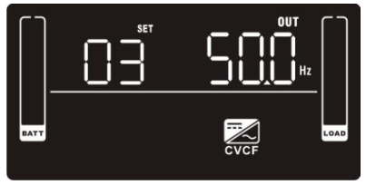
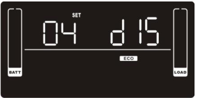
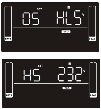
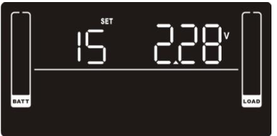
- ECO mode. You can enable ECO mode. This means that when the mains is within tolerance the UPS will have it’s inverter inactive thereby improving efficiency and hence reducing operating costs.
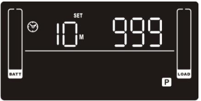
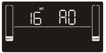
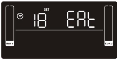
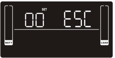
- Autonomy Limitation. You can set how long the UPS will remain on battery power for, rather than remaining on battery until it goes flat, preventing deep discharge and also allowing for the unit to be started when needed using a remote switch.
Remote Switch
The VFI Online UPS for door applications can be fitted with the Remote On/Off Relay interface card. By closing the on/off switch for 2 seconds this will toggle the UPS on and off. Since the UPS can be switched off it is important to ensure that the Bypass is enabled so power is always available.
If no mains is present and the UPS is online it will revert to battery operation until the autonomy limitation time is met, or the remote switch is used again to power the UPS down. If it is offline it will remain so until the remote switch is activated. It will then cold start on battery for as long as the autonomy limitation setting.
Note that the relay card also provides additional features. You can connect to external alarm panels, building management systems or SCADA applications. The UPS status can be communicated via the normally open, or normally closed (specified by onboard jumpers) for the following:
- UPS Fault
- UPS in Bypass
- UPS Battery Low
- UPS is online
- UPS is on battery
Note the standard relay card (AS400 card) can also be used but this requires an external 12V supply, or current limited 24V supply for on/off control.
Summary
You must enable the bypass in the UPS settings. If the UPS has bypass enabled and mains is present, it will sound the alarm to warn you every 10 seconds, but you get around this by turning it on.
You should limit the autonomy to a reasonable length of time. Enough to fully open and close the door – and then add some overhead.
You may enable ECO mode. Close power control will generally not be required.
You must have the relay card with remote on/off fitted to the UPS, or the standard relay card with an external voltage source.


