
We’ve created a short video (only 4 minutes) to explain the differences between line interactive and online UPS Systems.
We’ve created a short video (only 4 minutes) to explain the differences between line interactive and online UPS Systems.

A line interactive Uninterruptible Power Supply is characterised by its ability to raise the input voltage when it is too low, and to lower the input voltage when it is too high. This provides a degree of voltage regulation. This process is sometimes known as Automatic Voltage Regulation or AVR, however some manufacturers of AVR equipment may – and probably do – object to this as a line interactive UPS is a very loose AVR whereas a dedicated AVR device offers tight control on output voltages. A better description for a line interactive UPS System would be a “buck and boost” device.
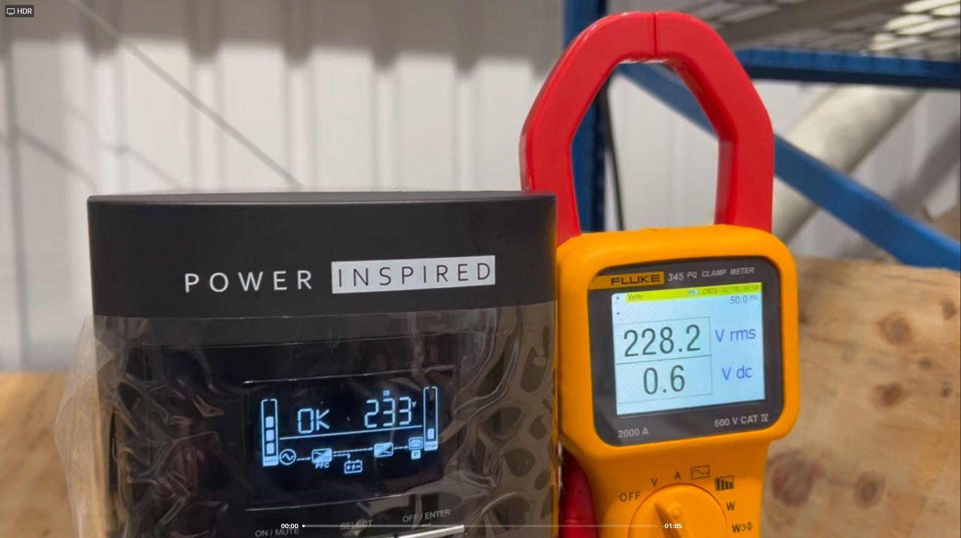
Here in this article I’m going to try and explain what one of our UPS does and for this I’m going to take the VIS2000B, apply varying voltage to it and observe the unit response. The VIS2000B is a good choice as the LCD display lets us know both input and output voltage so we don’t need to add any multimeters to the circuit. We’re going to modify the input voltage by means of a variable transformer, or a Variac. If you’re trying this at home don’t use a dimmer switch as these work in a different way.

Firstly we set the variac to nominal voltage, connect to the VIS2000B and switch it on. The display shows input voltage on the left at 230V and the output voltage on the right at 230V.
This is normal operation and so what comes in, goes out. What we will do now is increase the input voltage and observe.
As the voltage is increased the output voltage matches the input voltage until the buck trigger threshold is reached. This is set to be around the maximum voltage that the utility should provide which is 230 +10% = 253V.
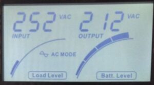
In our case at 252V the unit enters buck mode and reduces the high input voltage to 212V. [Also note that on VIS2000B the AC Mode indicator blinks.]
The lower threshold of voltage supplied by the utility is open to some debate. It is 230V -10% = 207V in much of Europe and was supposed to be the same in the UK. However the implementation date of about 8 years ago has come and gone and so officially in the UK the voltage is still set to be 230V – 6% = 216V. However other standards for products that are CE marked generally require equipment to be able to operate across the full spectrum of nominal voltages, so the output is aimed to be regulated within the realm of the EU, so 230±10% or 207V to 253V.
Raising our test variac to as high as it could go saw the unit maintain in buck mode with the output voltage rising proportionally with the input. In buck mode the input voltage is reduced by a nominal 16% or so.

Raising the input voltage even higher results in the unit disabling buck mode and reverting to battery operation.
As we reduce the input voltage the buck will at some point be deactivated and the unit will return to normal. There must be some hysteresis built into this or the unit would “chatter” eg switch constantly in and out at the threshold voltage.

In our test with the unit output reaching 207V a further reduction in input voltage caused the unit to switch out of buck mode and back into normal mode.
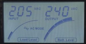
With the mains input voltage reduced further the output voltage tracks the input voltage until the boost threshold is reached at around the 207V mark.
Here the mains input is raised by around 17-18% in order to maintain the voltage within the nominal range.
Further reductions in the input voltage will keep the unit in boost mode until the output voltage can no longer be maintained within tolerance and the unit will revert to battery operation.
Raising the voltage the unit comes out of battery mode, straight into boost which then is disabled when the input voltage reaches around 211V.
To summarise, a line interactive unit attempts to maintain the output voltage within regulated limits for as long as possible without dropping to battery power. This is an advantage of over offline UPS systems that will have no option but to drop to battery instead of providing regulation, which would resort in lost loads due to UPS switching off due to depleted battery, or diminished battery life if the unit is regularly switching in and out of battery mode. However, they do not provide tight output voltage control. To achieve this online double conversion UPS systems provide a constant fixed output voltage regardless of the input voltage level.
Additional Notes with regard to the VIS2000B
One of the drawbacks of UPS Systems is the need for them to prevent a build up of heat and so many are fitted with forced cooling fans. In our VIS2000B the unit fan activates when the unit is “active” that is, on battery but also when it is in buck or boost mode. Users may find their unit enters buck mode when their mains is around the 250V mark as this will be activated should the mains hit 252V even momentarily. Due to the hysteresis effects the fan will not be disabled until the lower threshold is reached which is around the 246V mark. If this occurs, briefly switching the unit onto battery power will clear the hysteresis effect.
Note that we can change the threshold somewhat to effectively shift the buck and boost points higher by around 10V or so. This prevents the unit entering a nuisance buck mode and also makes the minimum output voltage more within the current UK spec but this does mean that the unit will allow voltages of 260+V through, should these be encountered. This is a factory setting that the Power Inspired technicians would be happy to undertake for you if required.

We were asked by a customers to come up with a UPS solution that will provide 8 hours of runtime for a load of 2300W to provide power for essential services at a new construction project in the Midlands.

The requirement was to deliver, position, install and commission the system and as requested we handled the project from Concept through to the Execution.
The first part is to ensure we have a UPS powerful enough for the load and make the decision on extra battery cabs or a bespoke battery solution. We could use one of our VFI3000T units, a 2700W unit – so powerful enough – and fit extra cabinets to this. The problem is we would need 19 additional cabinets to hit this amount of runtime! Clearly another solution was needed.
Our B16 cabinets (BCAB-B16) are very flexible and can support up to sixteen 100Ah blocks. Looking at the UPS requirement the best solution would be the VFI3000BL. This is a extended run UPS system, meaning it does not contain internal batteries but has a larger charger for connection to a large external cabinet. Most UPS only have a charger rated at around 1A, so connecting a 100Ah battery string would then require around a week to recharge following an outage, with the possibility that the battery would never get to 100% charge. The VFI3000BL has a massive 12A charger so will not suffer from such consequences.
The UPS has an input battery voltage of 72V, which is 6 blocks in the battery string. We can fit 2 strings in the B16 cabinet and this would give us a 72V 200Ah battery. Even with this capacity the runtime was still too short at only 4 hours. A second B16 cabinet would do the trick. With a further two strings added the achievable runtime was now calculated to be 9 hours and 48 minutes. Not only does this provide some overhead in the 8 hours requirement, it extends the working life of the installation as the batteries degrade with time and so 8 hours will still be achievable years from now. As longevity is an issue, the batteries used were our 100Ah deep cycle blocks, with 10 year design life (6FM100E-X). Not only that, but these blocks are rated at 100Ah when discharged at 10% of capacity, rather than lower cost blocks which are rated the same but at a 5% of capacity discharge (this is 10hour vs 20hour rating for those who know about such things).
So now the design of the system was finalised we had to plan the install on site.
First thing was to get our Wall mounted Maintenance Bypass Switch installed on site. This was sent to site in advance for the site electricians to install. This would allow ongoing power to be connected to their systems if they so desired and we can connect the UPS into play without affecting ongoing operations should this be required.
The B16 cabinet comes as a flat pack assembly which delighted the client. Previously for another site he had a battery cabinet delivered that weighed over a ton and had to somehow get this maneuvered into place. Not only did this prove to be extremely difficult, but the physical toll of this caused injuries to some personnel. In our case the two B16 cabinets and 24 batteries came on a pallet in the back of the company van and these were fork lifted off and placed just inside the building. We then decanted the pallet in manageable loads onto a trolley and wheeled these into position.

Note the finished B16 cabinet on the right, the second cab under construction and the wall mount bypass switch.
As usual, something unexpected does crop up and we try to plan for the unexpected. The client’s preferred position for the cabs was in the centre of the room but some ducts that was supposed be on the far left happened to be placed directly under where the cabs were supposed to be. However the footprint of the cabs and the UPS is so small we were able to put the cabs adjacent to the ducting and in a more preferred location. Once this was decided the first cab was assembled, followed shortly afterward by the second cabinet. For safety reasons we only have one person making connections to the cab at any one time. Here our qualified technician Ray (complete with ECS approval) did a sterling job.
Each cab is fitted with a DC breaker / isolator and the configuration is such that individual strings or the cabinets can be isolated to allow for relocation or service, not only maintaining power to the system (as you would with a bypass), but also maintaining UPS support.
Once the cab was assembled and tested, the UPS was connected and configured as per the clients requests. Positioning of the UPS is important to ensure adequate air flow and ease of operation and it was decided to be placed behind the cabinets in vertical orientation. This allows all cables to be neatly out of the way whilst allowing ease of viewing of UPS status. However this site was still a building site and so the floor was not yet finished and there was excessive dust that would be sucked into the UPS causing problems down the line. As a result the leads connecting to the UPS were made long enough for the UPS to sit in horizontal orientation on top of the B16 cabinet whilst work was completed and to be moved into position at a later date.

Once we’ve confirmed correct operation all was done and the client was then ready to connect his data cabinet up complete with UPS support.
Not only did Power Inspired provide a technically sound electrical solution, the physical properties were also a bonus to the customer, coupled with an ease of installation and a job that was completed in well under a day – including the all important ‘site inductions’.
A successful Project delivered with top-rate communications from our customer. Thank You R.