Isolation Transformer

Isolation Transformer. What you need to know

What is an Isolation Transformer?

An isolation transformer is a transformer used to transfer electrical power from a source of alternating current power to some equipment or device while isolating the powered device from the power source, usually for safety reasons. Isolation transformers provide galvanic isolation and are used to protect against electric shock, to suppress electrical noise in sensitive devices, or to transfer power between two circuits which must not be connected. A transformer sold for isolation is often built with special insulation between primary and secondary, and is specified to withstand a high voltage between windings.

Wikipedia – Isolation Transformer

Typical Electrical Arrangement

You probably don’t know it, but your mains supply is most likely provided to you via an isolation transformer. In the electrical substation that feeds your home lurks a huge chunk of copper and iron (the transformer) that takes relatively high voltage electrical power and converts this to our recognised 230-240V voltage that we all know. Your home is supplied with a cable from this transformer that has two conductors. One is the live conductor, and the other is a combined protective earth and neutral (PEN) conductor. (This is known as a TN-C-S system which is the most common in the UK. Other systems are available.)

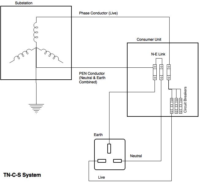
Once inside your house, the PEN conductor is separated into neutral and earth inside your consumer unit / distribution board aka fuse board. Note that here, the neutral and earth are bonded together which means that the voltage from live to neutral is the same as live to earth – a nominal 230V, and the voltage from neutral to earth is zero (as they are bonded together). Also note that the live conductor via the electricity board fuse, is split into feeds for your different circuits each protected with a circuit breaker or fuse. For extra protection a residual current device (RCD) may also be fitted. Whereas a fuse or circuit breaker will generally require many amps of current to trip or blow an RCD trips with around 30mA of current flow to earth (actually an imbalance between the live and neutral currents which in normal operation are the same). It is used to provide extra protection when contact with water may be experienced, or other potentially hazardous situations. Remember this!

The idea behind this arrangement is for electrical safety. Should a live conductor become detached from inside a piece of equipment and touch the earthed chassis then a high current will flow and blow the fuse or trip the breaker. The same result will be obtained if the equipment should develop a short circuit between live and neutral. If an electric shower has an exposed conductor that water comes in contact with, then there will be a smaller electrical current that will flow from live to earth and this is detected by the RCD which will trip and remove electrical power to the faulty piece of equipment (and everything else on the same circuit). Handy if you’re naked in an earthed bath.

So now we have three conductors at our wall outlet. Assuming we are connected to earth (as we are standing on it), then we will receive an electric shock if we happen to come into contact with the live conductor, but we will be safe if we touch the neutral conductor (as Neutral to earth voltage is zero). If we’re isolated from earth (eg with rubber boots) then we could touch the live conductor and not receive a shock. If we touch both the live and neutral conductors then we will get a shock of course.

The Isolation Transformer for Safety

So how can the isolation transformer be used for electrical safety? It all comes down to what a transformer actually is. In the simplest terms it is two coils of wire around an iron core. The incoming coil – called the primary – converts an electric field into a magnetic one. This magnetic field then induces an electric field on the second coil and hence a voltage appears on the output of this coil (called the secondary). By varying the number of turns in the coils the voltage can be stepped up or down, but in our case the number of turns are equal and so the output voltage is the same as the input voltage. However, the point to grasp here is that there is no electrical connection between the input and the output. The link is done by magnetism. This means that the output is “isolated” from the input and hence the term isolation transformer!

The output of the isolation transformer still has a nominal output voltage of 230V between its output conductors, but there is no link to earth. This means that you can safely touch either conductor without risk of electric shock. You will still get an electric shock if you touch both conductors however!

It is important to note that with an isolation transformer, a device that may have an earth fault that would trip a circuit breaker or blow a fuse will work just fine. In fact, isolation transformers are used for this very reason in certain applications where the sudden disconnection of power due to an earth fault may cause even larger hazards (such as in chemical plants, or in operating theaters). In such cases monitoring is usually provided so that an alarm is raised should this occur.

In the diagram above, taking an installation without an isolation transformer, the device has an earth fault (for example a live conductor has shorted to the chassis). Since Neutral and Earth are bonded in the consumer unit the system sees this as a short circuit and so a large current will flow which will blow the fuse or trip a circuit breaker. It would also trip an RCD if fitted.

When an isolation transformer is put in circuit, nothing will happen. This is because the secondary live and neutral are no longer live and neutral. They really should be called phase 1 and phase 2 hence I’ve put them in quotes. Since they are no longer live and neutral there is no reference to the incoming earth, and therefore no fault current can flow. In this case since there is a fault from “live” to earth, this “live” effectively becomes the equivalent of neutral and the “neutral” effectively becomes live. In the diagram above you would have 230V between “live” and “neutral”, 230V between “neutral” and earth and zero volts between “live” and earth.

However, the main use of an isolation transformer for safety is when people are working live an accidental touch of a live conductor will not cause an electric shock, or that there is risk of damage to cables etc. such as in building sites.

Another consequence of this is that “earth leakage” that is, a trickle of current from live to earth, caused by mains filters, is eliminated. Since there is no direct earth connection, then there is nowhere for the earth leakage to flow to. This can be advantageous in patient vicinity applications or to reduce earth leakage from several devices to avoid nuisance RCD trips.

Use of the Isolation Transformer for reducing electrical noise.

The transformer, being a coil, has what is known as inductance. Inductance is a barrier to high frequency signals. Electrical noise is a high frequency signal and so the transformer acts as a block to this. Other power problems can also be reduced especially if there is an electrostatic screen in the transformer construction which is connected to earth. Any electrical transients between the power conductors and earth can be effectively reduced using this method.

Disturbances between the power conductors can be reduced by the inductance but not eliminated. This is why in dedicated power conditioning devices that incorporate isolation transformers, further filtration is placed on the secondary side of the transformer to reduce this further.

Rather than go into details about this, this piece makes for good bedtime reading.

Or you can just take my word for it.

Redoing the N-E Bond

In complex electrical installations, or some where the wiring may be old, have poor connections or otherwise has excessive impedance, the voltage between neutral and earth can increase, particularly at the furthest points from the distribution board and particularly where high currents are involved. This may, or may not be a problem for your electrical equipment. You could just rebond the neutral to earth again, but electrical codes do not allow for this. However since the secondary is isolated from the primary you can safely derive a new neutral and earth by bonding these together at the secondary of the isolation transformer. This is also done to eliminate noise between “neutral” and earth – as you are shorting it out.

There is a safety concern when doing this however. If, for example, equipment in areas that may come into contact with water (for example laboratories) it is desirous to protect this circuit with a residual current device. This is because water is a pretty poor conductor of electricity and in the event a piece of equipment becoming splashed with water not enough current would flow to blow a fuse, but enough current could flow to give somebody who may be in contact with the water and earth a nasty electric shock. Note that is only takes several milliamps of current to cause heart beat disruption.

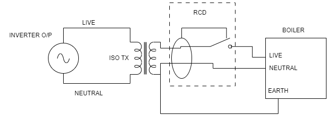
Take the scenario above. To protect operators working on equipment with the risk of water contacting live conductors the circuit has been fitted with an RCD. Should water be spilled onto the equipment and come into contact with live conductors a leakage current will flow causing the RCD to operate. This will disconnect power from the equipment and leave the operator safe.

In the next scenario, an isolation transformer has been fitted and supplies the equipment. Should water be spilled now any contact with live conductors will only reference the conductors to earth. No current will flow and hence the operator will be safe and the equipment will continue to operate.

In the final scenario, the isolation transformer has had the earth connected to one of the secondary phases creating a new effective neutral-earth bond. Should water now be spilled on the equipment and come into contact with live conductors a current will flow from the phase end of the transformer, to the equipment, through the water to earth and then back to the transformer. Since this current path is contained within the secondary of the transformer, the RCD will not detect an imbalance and will therefore not trip. The operator is now in an unsafe environment with the potential for an electric shock as they may become the lowest point of resistance for the leakage current.

It is not only water where such hazards can exist. I recall being told of the case of an unfortunate checkout operator at a major grocery store chain. Unbeknown to her, an electrical cable feeding some equipment had become entangled in her chair mechanism. As she swivelled in the chair this caused a cut in the insulation of the cable which then contacted the live conductor. This circuit was not protected by an RCD but only by circuit breakers. It would therefore take a fault like current to trip the breaker. In this instance the chair made a poor connection to earth and so the chair – and the unfortunate operator – were now at live potential. Everytime she touched something that was earthed – such as the till or conveyer mechanism – she received an electric shock. If the circuit was protected with an RCD then this would not prevent an electric shock but the severity would be reduced and it would only happen once, rather than the multiple times it happened to this poor lady until power could be removed. The retrospective action was indeed to fit RCDs (and do this in all stores). If they were to fit an isolation transformer then the operator would not have received an electric shock at all. No fault would be apparent – save for a visual inspection. If they were to fit an isolation transformer with a N-E bond on the secondary, then this would have negated the effect of the RCD rendering another dangerous situation for the operator.

Transformer Regulation

Transformers are not perfect and impedance exists in them that causes a volt drop within the transformer when current flows. The more current that flows the larger the volt drop and so the output voltage falls. The regulation of a transformer is the difference in the no-load voltage to the full load voltage expressed as a percentage. Poor regulation can introduce other problems into a circuit. For example, if the load is non-linear and takes current in high value chunks – such as in rectifiers, then the poor regulation can cause waveform distortion and introduce voltage harmonics into the system. Other problems include the voltage falling too low and causing under-voltage protection systems to operate.

UPS and Isolation Transformers

Before I go into UPS with isolation transformers it’s probably worth mentioning what happens with transformerless UPS Systems in the event of an earth fault like described above. Earth leakage is not eradicated using a UPS. In fact it is cumulative so the earth leakage of the UPS is added to the earth leakage of the connected loads. This is a consideration for pluggable UPS but that is the subject of another article. If an earth leakage event occurs that trips the RCD then power to the UPS will be lost and the UPS will do what it is meant to do and that is continue to provide power to the connected load – even if it does have a fault. Note I’m assuming here that this is a fault in the order of tens of milliamps- enough to trip the RCD but not enough to blow a fuse or trip a circuit breaker. This you would feel is a hazard. However, when a UPS is operating from battery it will have (pluggable systems – not always the case on hardwired systems) a back-feed relay. What this does is open to prevent the output of the inverter being present on the incoming supply pins on the UPS. This is effectively the same as isolation. The load is now isolated from the source and therefore no earth leakage current will continue to flow and therefore no hazard will exist.

When a UPS has an isolation transformer this provides added power protection but it does require certain considerations. Firstly, it requires a big chunk of copper and iron to be added to it, substantially increasing its weight and physical size. As described above, the creation of a neutral-earth bond on the UPS secondary causes any RCD protection to be redundant, so it is preferable to have the transformer floating. On hardwired UPS systems, if a N-E bond is desired this can be added by the site installers quite easily and any RCD protection installed downstream of the UPS. Also, where in the UPS circuit should the transformer go? Should it be on the input or the output?

If it is on the input, then the UPS has the added benefit of the protection afforded by the transformer. It means that the earth leakage of the UPS (and connected equipment) is zero as measured on the input to the UPS.

If it is on the output, then the UPS output will always be consistent whether or not it is running from battery power or in normal operation. This would be especially important if a N-E bond is required.

In my opinion we consider an input transformer to be the best option, coupled with a truly floating output. This is the safest configuration and one we have incorporated into our TX Series UPS systems.

Edit – Floating Voltages

Adding this to the original article to explain in detail why the output voltages to earth are as they are.

If we take our isolation transformer on which the output secondaries are not connected to earth. Try as we might there will always be some parasitic capacitance between the output phases to earth, the impedance of which we will call Zp.

Then we measure, (using a high impedance voltmeter) between Phase 1 and Phase 2 and we will get the output voltage Vo. Now measuring between Phase 1 and Earth, what will we expect to find? We are measuring the voltage across the parasitic impedance Zp. Assuming this is the same between phase 1 and earth as is between phase 2 and earth, then the voltage measured will be Vm = Vo (Zp / (Zp + Zp) ), or Vm = Vo/2, eg what we measure is half the output voltage. So for a 230V transformer we would expect to measure around 115V.

If we connect a piece of equipment to the transformer that contains an input filter, then we will find there are capacitors intentionally connected between the input phases and ground. Ignoring Zp (as Zc≪Zp), then Vm = Vo(Zc/(Zc+Zc)) Eg half Vo again.

This is why the measured voltage between phase and ground tends to be around half the transformer output voltage. I can see why at first glance this may cause concern, as it appears that we have a high voltage to earth even via our isolation transformer. However no current will flow (and hence it is safe) if we make a connection between any phase and earth. All we do is now reference that phase to earth.


Comments

54 responses to “Isolation Transformer. What you need to know”

  1. […] The way to solve common mode power problems is to isolate the load from the supply. This is exactly what the TX Series does. The in-built isolation transformer creates a new live and neutral, and the online double conversion technology then ensures a high quality stable output. An an added advantage the isolation transformer can provide a safety shield against electric shock which is particularly important in applications where water and electricity may mix. Again, hospital laboratories are a prime candidate. Thus the TX Series can also be defined as Laboratory UPS System. Click for further information on the isolation transformer. […]

  2. Rajesh T T avatar
    Rajesh T T

    Can you suggest in this which circuit is more safety for patients who is going to take a treatment in medical equipment? with less leakage current

    1. Tony Bell avatar
      Tony Bell

      An isolation transformer upstream of the load without a N-E bond will remove any earth leakage and hence any touch current. This will meet medical requirements, eg <0.5mA for IEC601, but note other requirements in this standard may apply.

  3. N Trueman avatar
    N Trueman

    If you have an N-E bond on an isolating transformer (it seems to be the regulation that all such transformers are supplied with this bond in place by default) and then try to test DUT with an oscilloscope this can create a dangerous situation (and destroy the test equipment). So is it best to use isolation transformers with or without N-E bond?

    1. Tony Bell avatar
      Tony Bell

      The problem with most oscilloscopes is that the GND is just that – earthed, which would cause a short circuit if you happened to connect the GND of the scope to a live conductor in your DUT. So to do this safely you must have no N-E bond. This way your DUT is isolated from the scope GND and therefore the connection of the scope GND to a live conductor will only reference that part to real earth without causing any short.

  4. Tushar avatar
    Tushar

    Hello,

    Recently there was short circuit in the transformer feeding power to our school and few homes around. The short circuit was caused by group of squirrels. Due to short circuit a lot of electronic equipment got damaged in school. We have mcb installed but I guess they only trip when short circuit happens in output line which they are guarding. In our case short circuit happened before the mcb as transformer is located outside school premise. So wanted to know what all safety devices are available which can be installed in school to provide safety in this scenario.

    Also if anyone can suggest safety devices for lightning protection that will be great.

  5. Bengt Ragnemalm avatar
    Bengt Ragnemalm

    In your pictures any grounding of the ISO TX is done at one side. But here in Sweden the typical approach is that a ground to the ISO TX is made at the secondary sides mid point. This in effect halves the leakage currents. You also say that an floating ISO TX is to prefer, and I agree to that. But I have very hard to decide the correlation between the three typical grounding schemes:
    1. No primary ground or no ground coming through from primary to secondary. ISO TX has ground on the output side.
    2. Primary ground and ground is coming through to secondary side. ISO TX is NOT grounded.
    3. Same as nr 2 but ISO TX is grounded.

    The situation that I usually consider as most critical in the above situations is there we have a leakage through the patient to ground. A ground that goes through the ISO TX or not should make all the difference here.

    ISO TX with mid point ground just makes the confusion larger but that is what I have to understand as well.

    1. Tony Bell avatar
      Tony Bell

      Thanks for your comment. What you seem to be describing is a split-phase or sometimes called balanced system, where you have a 230V (L-N & L-E) system and, using an isolation transformer with 2 secondary windings create a 115-0-115 system, with the zero being the earthed centre tapped point. I’m not sure that this system is guaranteed to half the earth leakage as you now have two phases that can contribute to the earth leakage, thereby making the overall leakage the same. However, to avoid earth leakage travelling from the output transformer to “true earth”, this can be achieved in scheme 1. The problem here I feel, is how do you ensure that the newly created earth will not somehow be referenced to true ground? You would have to take steps to ensure this wouldn’t happen, but if you could then this would satisfy your requirement.

      In scheme 2, the output is not earthed so you no longer have a 115-0-115 system, but simply a 230V floating system. This should remove the possibility of earth leakage through the patient, but you would need to check the operation of the equipment connected is OK without an earth reference.

      Scheme 3 would reference the output phases to true ground, thereby allowing leakage from the output transformer to true earth, through the patient. Note, though that this is only the earth leakage generated by the connected equipment, not any current which may be flowing from the source phases to ground, so should be safe.

  6. I have taken voltage reading across secondary winding of isolation transformer

    P-N=230 volt
    N- E=110volt
    P-E=138volt
    I confused how N- E comes 110 volt
    Plz guide me

    1. Tony Bell avatar
      Tony Bell

      With an isolation transformer floating with respect to earth, when you measure any of the phases to earth you will get phantom readings. You normally find that due to filter networks on any loads connected that the P-E and N-E voltages tend to half way, so 115V for a 230V system. However if nothing is connected then these voltages will just be arbitrary.

    2. srinivasulureddy avatar
      srinivasulureddy

      I’m also facing same problem, can any one explain with detail why Output N-E=110V coming????

      1. Tony Bell avatar
        Tony Bell

        I’ve edited the document to explain the output voltage phenomenon on isolation transformers.

  7. […] this article on isolation transformers for further […]

  8. Hello,
    Two questions:
    – If an isolation transformer is installed on a steel boat, is it better to have an N-E bond (the earth being connected to the hull of the boat)?
    – Would it be a good idea to add a RCD and a correctly sized circuit breaker before the transformer if unsure of the shore protection to protect the input circuit of the transformer? The output circuit will also be protected by a RCD.
    Thank you.

    1. Tony Bell avatar
      Tony Bell

      In reply to Ines:
      I’m not 100% but I’m sure there are specific regulations you need to comply with for installations on boats. You will need to confer with an expert in that field I’m afraid. As for your second question, you should always fit an RCD according to the 18ed Regulations. (Unless there’s a damn good reason not to, and there’s not here).

  9. I have nuisance tripping of a 30mAmp RCD due to the transformer having the secondary earthed. I removed the earth terminal from the secondary and just bonded the earth to the chassis of the transformer. ( I am finding it hard to understand why the RCD is tripping since the earth is on the secondary side of the transformer.)

    1. Tony Bell avatar
      Tony Bell

      I’m not sure if you mean the RCD is upstream or downstream of the transformer, but one way to fault find is to remember that RCD’s only operate when there is an imbalance between the live and neutral conductors. The idea being that some phase current is leaking to earth somewhere (not necessarily to the earth conductor).
      An isolation transformer stops leakage downstream unless the earth is referenced to one of the output phases. Hope that helps

  10. Can anyone help? We have a building services feeder panel, this has a 4 pole MCCB on the mains in feed. This then supplies several feeders. 2 of the feeders supply a server cabinet and RIO panel, both of these are Ups backed with an isolation transformer on the in feed side, each has a 63A type D MCB feeding the isolation transformers (ups manufacturers state this is fine) If we loose the supply to either of the Ups backed panels by isolating it’s feeder on the building services panel the ups battery back up supports the loads. If we then reinstate the mains the ups changes back to mains feed, all is good. The problem occurs when we open the 4 pole MCCB feeding the building services board, both ups change to battery back up and support the loads. When we then close the 4 pole MCCB it will trip one of the 63A MCB’S feeding the isolation transformer (this has been done several times with one out of the two MCB’S tripping, sometimes neither will trip) We have had a clamp ammeter on the 63A MCB’S reading a high current on the neutral (sometimes) . Our thoughts so far are is it the fact its a 4 pole MCCB breaking the neutral causing problems with the neutral/earth path? Could there be a problem with one of the other loads fed from the building services board causing this? Or just an earthing issue? Real head scratcher, any ideas or pointers would be great. Forgot to mention the feeder isolators for either of the ups backed boards are 3 pole with a solid neutral link.

    1. Tony Bell avatar
      Tony Bell

      If I’ve read this right you’ve got 4pole MCCB feeding 2x 63A 3pole MCB, feeding a 3ph ISO TX feeding a UPS? Is the UPS Neutral derived from the ISO TX star point?

      If so, then this is a strange one.

      If not, the issue is more than likely the 4 pole breaker. Some UPS don’t like having the input neutral being lost. One way of testing would be to short the Neutral link in the 4way MCCB and see if the problem occurs. If so, then something else is awry.

      1. It’s a 230v p+n iso TX. The 63A is a 2 pole mcb. That is what we thought maybe the issue, the fact the 4pole mccb is cutting the neutral. Do you know if its within regs and not a safety concern to earth the neutral on the primary side of the isolation TX’S? Did a little research could only really find information on N/E on the secondary side. We are going to test the neutral theory next visit. Thanks

        1. Tony Bell avatar
          Tony Bell

          “Do you know if its within regs and not a safety concern to earth the neutral on the primary side of the isolation TX’S?”

          No- you cannot do this on the primary side of the iso TX. Doing so would violate the regs. Although in TNCS system the Neutral & Earth are bonded in the consumer unit, they need to be separate throughout the infrastructure. Bonding them outside the CU would result in the earth path carrying a proportion of load current.

  11. I have a concern I hope you can help with, Tony:

    If the input ac plug of an isolating transformer (with a secondary N-E connection) is plugged into the wall socket upside down (as can be achieved with European plugs, but can’t with UK plugs). Would that mean that you have a L-E connected isolating transformer? What are the safety implications of this of switching L and N in a N-E connected system? Would electrical noise increase also?

    1. Tony Bell avatar
      Tony Bell

      It’s not a concern. The output of the isolation transformer is floating with respect to the input, and rather than thinking of the outputs as being live and neutral think of them as phase 1 and phase 2. Whichever phase you bond to earth will then become the output neutral.

  12. Tom Warner avatar
    Tom Warner

    This can have disastrous consequences if you lose your earth bond to the neutral in some applications. This can occur quite easily, If you have a UPS system supplying a medical installation and the supply to the UPS is disconnected then you find that the UPS output continues to operate without any reference to earth. I have seen this on a large 1,000kw 3ph ups where when the input circuit breaker is operated the UPS output becomes floating from earth. This is not good in a computer suite. and creates complications.

  13. Lak-Jay avatar
    Lak-Jay

    Can some one help me out to solve my problem.. My country uses TT system for power distribution with 230V under single phase.
    I am planning to use Garden lights (decorative) with 230V fed through 2ft buried armored cables. As an added safety I am planning to feed them with 1:1 Isolation Transformer (230:230V) that would keep the fault current zero from mains circuit at an event of a failure or a ground.
    Under this scenario the circuit would operate as i expect but if by any chance – if one phase of Secondary side of a transformer gets grounded the system would not detect but continue to operate posing a hazard to the others who would touch the any part of the other end by mistake.
    Can some one suggest an answer to this scenario that could rise up?

    1. Tony Bell avatar
      Tony Bell

      IMO the likelihood of this being a hazard is very low since it is a double fault condition that needs to occur, eg, you need to have a fault that shorts a phase to ground, and then somebody needs to be grounded and touch the other phase. Remember that any electrical system poses a risk of electric shock if somebody touches both phases. The idea is you make it impossible for them to accidentally do so. That said, if you want to protect against this, the only was I can see is to bond one of the secondary phases intentionally to ground and then fit a RCD. This will trip and disconnect power if the “live” phase should be connected to ground either by fault or by somebody touching it.

  14. Today I have seen an installation where we had a 3kVA galvanic isolation transformer installed in the circuit. Before the transformer when I measured betwen neutral and earth I got a reading of 0 volts (which is normal as it is the TN-C-S system), but after the transformer when I measured between the earth and the neutral I got a reading between 48V and 62V depending on the circuit after the transformer. Is this normal? Is it still safe to have the earthing connected to the metal casings of the equipments powered through the isolation transformer?

    1. Tony Bell avatar
      Tony Bell

      This is absolutely normal and just as you would expect as the voltage on any of the phases wrt ground is floating. Earthing equipment is perfectly safe.

      1. As the equipments powered are professional sounding equipment (this is why it is used isolation transformer for the purpose of noise mitigation) can this Neutral to Earth value of around 50-60 volts could pottentially affect the named equipments ?

        1. Tony Bell avatar
          Tony Bell

          I would of thought there would be no problem, but you should check with the manufacturer to be sure. You could always bond the output “neutral” to earth. This would give perfect zero N-E voltage, but will need additional safety measures as mentioned in the article.

  15. Hi, In your explanation of the TN-C-S system you state: “Once inside your house, the PEN conductor is separated into the neutral and live conductors (via a fuse) inside your consumer unit / distribution board aka fuse board.”
    Should this be the PEN is separated into the neutral and earth conductors?

    1. Tony Bell avatar
      Tony Bell

      Thanks, the grammar could have been better, edited.

  16. Mike Birch avatar
    Mike Birch

    Hi. I have an isolation transformer test bench which our Electrical Contractor has rejected during appliance testing as it is not earthed. While I understand this is the purpose of an Isolation Test Environment, are there any documents available to allow this to be passed and / or signage available to locate for the test bed?

    1. IMO your contractor is probably right. You should earth the test bench as you need to protect against a fault on the input power side. The output L/N should remain floating to protect your operators, but this doesn’t negate the need to earth. The only way of avoiding an earth would be if the whole set up was double insulated and treated as a class II appliance.

  17. Daniel avatar
    Daniel

    Trying to get my head around this stuff – grateful if anyone can help…

    I am connecting up a heat pump for an existing domestic pool. Given I cannot access existing steel in concrete, I’ve been required by local authorities (Canberra, Australia) to connect the appliance via an isolation transformer.

    I’ve connected A+N+E to the line side and only A and N from the secondary to the heat pump.

    I’m wondering whether I should install some load protection on the the secondary side of the transformer? Could an RCD on the secondary side serve as higher protection, should something happen internally? And would that even work? I guess I’m trying to work out if it is possible that the water could somehow get a hazardous potential from the unit some how…

    Thanks in advance!

    1. What you’re trying ultimately to do is to protect the pool users from electric shock. The fear by the local authorities is that if there was a fault and the water could come into contact with live electricity, the steel (which is not earthed) could act as a conductor to earth via a person, should they happen to touch it. The idea of the isolation transformer is that it allows the system to be safe even in the event of a fault. An RCD on the load side won’t work in any case unless you rebonded the earth to the neutral and you would then have the same dangerous scenario.

  18. Steven Galione avatar
    Steven Galione

    If an RCD socket is connected to a 230V isolating transformer, should the earth tag on the socket be connected to the incoming earth from the supply side of the transformer or should this earth not be connected at all? Thanks.

    1. It would be good practice in this scenario to keep the earth, just to ensure all earths are at the same potential, however the RCD will not work at all unless the Neutral is bonded to the earth, which negates the safety aspect of the isolation transformer. Performing the NE bond is only of use for noise suppression or creating a new circuit with no earth leakage back to the primary.

  19. Steven Galione avatar
    Steven Galione

    Thankyou Tony, so is fitting an RCD type socket a waste of time when used with a 230V isolating transformer? Should I just fit a non-RCD standard socket and not connect the earth, or should I fit the non-RCD socket and connect the earth? Thanks, Steve.

  20. Harry avatar
    Harry

    Hello, I discovered this your very good explanation about risks with an RCD & Isolation transformer. Thank you for that.

    However: I wonder as to avoid an NE-bond after the isolation transformer: can’t we just place
    an RCD after the isolation Transformer,
    on its both Phases & get Touch safety ???

    Best regards, Harry.

    1. The isolation transformer gives you touch safety on any of the phases (to earth not to each other obviously). Fitting an RCD is irrelevant with no NE bond as it will never trip.

  21. Richard avatar
    Richard

    I want to use an inverter to power a worcester bosch gas boiler. This boiler requires a N-E bond for the flame detector circuit to work.
    The inverter has a floating output, and cannot(according to manual) have its output bonded to E. Would it be possible to connect the inverter through an isolating transformer, with the secodary N-E bonded, and then an RCD downstream of that?

  22. If a fault develops between the live conductors and a metal case of a class 1 appliance which is supplied from an isolating transformer , can you receive an electric shock then?

    1. No. You won’t receive an electric shock provided the “neutral” conductor is not referenced to earth in any way.

  23. Mike Tyllyer avatar
    Mike Tyllyer

    Hi Tony, I’ve just noticed your reply recently to a guy concerning using an inverter and an isolation transformer to power a Worcester Bosch gas boiler and I have exactly the same issue. Could you possibly provide a sketch showing the wiring set up.
    Many thanks.

    1. Inverter-ISOTX-RCD-Boiler [Apologies for late response]

  24. Thank you so much for the detailed information. I have a question regarding the scenario with the equipment getting wet. What if N is bonded to Ground(ground pin on output side) on the secondary side but not bonded to earth?

    1. Still unsafe. Assume that water falling on the equipment provides a conductive path from the TX phase conductor to the chassis but of high enough impedance not to blow the equipment fuse (likely). A user in contact with the water and the equipment chassis would then become part of the conductive path and then receive a shock. Only by having the equipment earth floating wrt to the isolation transformer phases is the user safe. You would need to install an RCD on the output much like the inverter question earlier.

  25. Thank you for your prompt response. To make things brief, I am trying to break the ground connection from the outlet to a computer. Would you be so kind as to tell me which of these three scenarios would be the safest?

    1.Similiar to the inverter example above but with earth attached to The body of the isolated transformer but not carried over to the output. Neutral and ground bonded on the output as in the illustration with the RCD on the output?

    2 isolated transformer with metal body grounded to earth but ground completely removed on output (not connected to neutral just absent). RCD can be installed on output side but not sure if it would do anything in this scenario?

    3. No isolated transformer ground pin removed on PC via adapter and RCD at panel box?

  26. Hi Tony, thank you for the great info!

    I’m facing similar dilemma as in posts 21 and 23, except it’s a single-phase 110V UPS that I need to put in front of a condensing boiler. Boiler fails unless N is bonded to E. But UPS as per updated UL requirements breaks N path when running on the battery power. Which makes UPS N output float with respect to the Earth since N is only bonded to E back at the breaker panel. UPS still preserves E continuity during battery operation.

    So I consider the best grounding and GFCI (RFD) setup for a single phase isolation transformer downstream of UPS to overcome UPS floating output.

    In your response to Mike Tyllyer, is there specific reason there is no connection of the secondary side NE to the primary side E conductor? Any harm to add one?

    Secondly, once secondary NE is bonded to primary side E, is there an issue omitting the RCD / GFCI on the output to avoid service interruptions due to RFD / GFCI failing with age?

    Under normal operation boiler is connected to utility power and does not require RFD / GFCI protection. All of it’s metal piping and the case also happens to be permanently connected to the same metal pipe that serves as a grounding electrode and where panel N & E are connected.

    All of the above is on a Canadian domestics 110V single phase L – N – G(E) branch circuit. And we don’t have RCDs at the panel by default, just the regular current breakers.

    Thank you!
    -Victor

  27. In your response to Mike Tyllyer, is there specific reason there is no connection of the secondary side NE to the primary side E conductor? Any harm to add one?” – No, the earth wasn’t shown as the OP suggested it was floating, and also the main point was on creating the secondary N-E bond. Passing the earth through is OK. As long as the output has appropriate protections as defined in your code, an RCD is not needed. In UK current regs state RCD should be used unless there is a good reason not to, so I would always recommend there is one, but I can’t advise you other than that.

  28. Tony Whittaker avatar
    Tony Whittaker

    I have bought a toothbrush with wireless charger, which has a normal mains plug fitted. The instruction sheet says that polarity matters for this piece of equipment. However, I would have preferred to replace the mains plug with a sealed waterproof two-pin plug and use it in our bathroom isolating transformer, in the way we have always used toothbrush chargers. My question is: I understand that an isolating transformer has no polarity, that is to say, each connection is oscillating at from +120V to -120V AC, creating the required 240v AC between the two pin sockets. Therefore, my charger unit would be happy for the two-pin plug to be inserted in the socket any way round.

    Thanks for your advice

    1. Hi Tony, yes that seems absolutely fine to me. I would have thought the device was a Class II appliance anyway (eg double insulated and no earth connection). Check for a double square symbol ( a square within a square) on the rating plate. In which case polarity has no meaning and you can connect to any two pronged adapter – not just those fed from an isolation transformer.

Leave a Reply to Tony Bell Cancel reply

Your email address will not be published. Required fields are marked *

This site uses cookies for functional, security and analytical reasons. To use this site cookies must be enabled. Please refer to our Privacy & Cookie Pages for further details.

Google Chrome:

Mozilla Firefox:

Microsoft Edge:

Safari:

Opera: