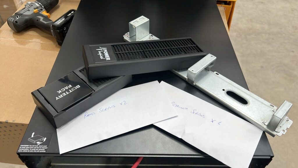
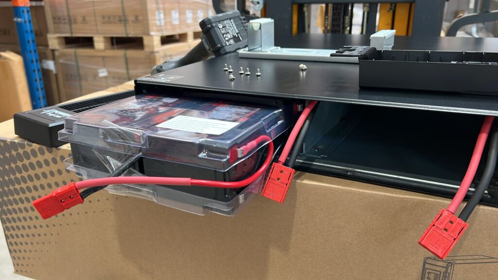
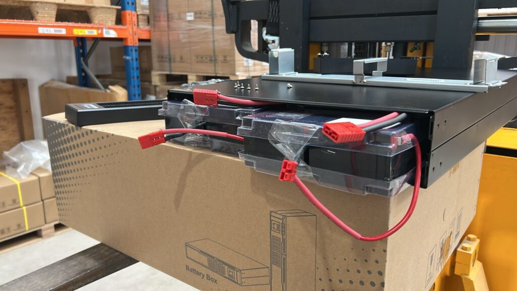
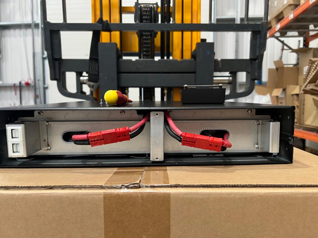
Following on from how to install the battery trays in the VFI-RT+ UPS I thought it a good idea to then explain some of the settings that you can set to ensure the UPS works how you want it to.
Note that some of the settings can cause mis-operation or even damage so should only be performed by persons knowledgeable about what they are doing. Reading this guide will help!
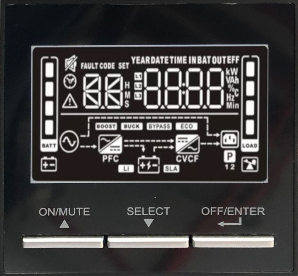
The UPS settings are accessed via the LCD screen. No software is required. First of all make sure the UPS is in standby mode by pressing the OFF/ENTER / ↲ key for several seconds. The unit will either enter bypass or standby mode (if it wasn’t already). Now we are ready to enter the UPS settings screen. To do this press and hold the SELECT /▼ key. After around 3 seconds the UPS will enter the settings menu.
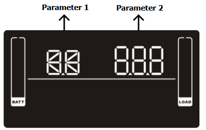
The Settings screen shows two parameters. Parameter 1 is usually the number of the setting, but maybe some additional information when adjusting the setting value. Parameter 2 shows the settings current value, or the value you want to set it to. To navigate the settings press SELECT ▼ to increment the menu, the ON/MUTE ▲ button to decrement (I know this is counter intuitive with the arrows pointing up and down but think of the arrows more as next and previous). Use the OFF/ENTER ↲ to enter the settings and the ▼ or ▲ to select the desired setting.
Press ↲ at the desired value to exit back to the settings menu.
Note that icons will also appear on the LCD to guide you.
UPS Settings
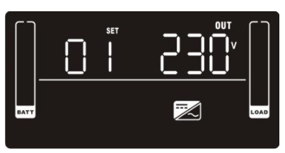
Setting # 1 is the output voltage when on inverter. Your choices are 200, 208, 220, 230 or 240V. Note that at 200V the output power is derated by 20%. The default is 230V.
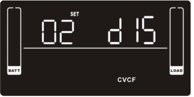
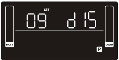
Setting # 2 is CVCF mode or Constant Voltage Constant Frequency. In normal use the VFI RT+ will track the input frequency and auto set to either 50 or 60Hz depending upon input. In CVCF mode you can output either 50 or 60Hz regardless of the input frequency. E.g. you can have 50Hz input and 60Hz output – useful for operating high voltage US equipment in Europe that may not be suitable for 50Hz operation. The converse is also true, e.g. output 50Hz from a 60Hz supply. In addition if powering from a generator whose frequency may be unstable this is a good option to ensure the load is always provided with high quality power. Your options are ENA for enabled or dIS for disabled. CVCF is disabled by default.
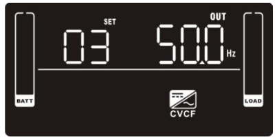
Setting #3 is the converter frequency you want to run. If CVCF mode is ENAbled, it will set the frequency to either CF 50 or CF 60. It also sets the initial frequency in battery mode. For example if you cold start the unit the inverter will output either BAT 50 or BAT 60
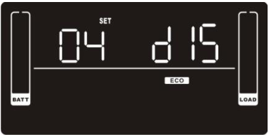
Setting #4 is ECO or Economy mode. In this mode the UPS will supply the load in bypass with the inverter ready if need be. In this mode the output is variable and there is a slight break in power during transition, but since there are no conversion losses the efficiency is much higher and therefore running costs lower.
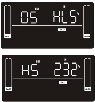
Setting # 5 allows you to vary the amount of out of tolerance voltage the unit will allow in ECO mode before reverting back to an online unit in both high voltage and low voltage. Your options are from +7 to +24V (default is +12V) for high line and -7V to -24V (default is -12V) on the low line.
So if you’re concerned about using ECO you can still have a fairly narrow voltage window by setting to within your acceptable parameters.
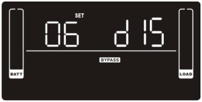
Setting #6 is Bypass. This is an important setting and should be given consideration depending upon your power quality / power continuity needs. If the UPS goes off for any reason e.g. fault or somebody switches it off, then if the bypass is disabled then power to the load will go off. This may be a desirous situation as you may want to control the output power from the UPS, or you may not wish your load to receive any unconditioned power. However, if power continuity is more important then you should enable bypass. This way if the unit is switched off you will still have power to the load. Note that this sometimes causes people to forget to actually turn the UPS online. As a reminder if the UPS has bypass enabled and power is present it will beep every minute or so to warn you.
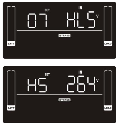
Setting #7 is the bypass high and low points. If bypass is enabled the UPS will switch off bypass if the input voltage is outside the parameters set here. You can have between 230 and 264V for overvoltage and from 170 to 220V for undervoltage. The defaults are 170V and 264V.
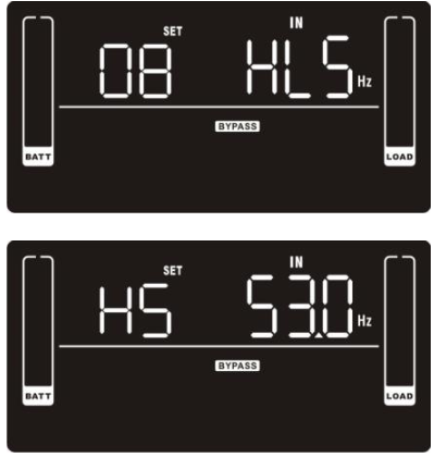
Setting #8 is a bypass setting again but this time the frequency. Dependent upon which frequency mode is set (Setting #3) the options you have are from 45-49Hz (default 47Hz) to 51-55Hz (default 53) for a 50Hz system and from 55-59Hz (default 57Hz) to 61-65Hz (default 63Hz) for a 60Hz system.
Setting # 9 is the programmable outlet setting. On the rear of the unit there is a bank of outlets that are “programmable”. It is used for load shedding purposes when on battery power. For example you may have some non essential equipment that you need minimal backup for but others you want to maintain for as long as possible. So the equipment that is non-essential (or perhaps will shut down automagically) can be plugged into he programmable outlet to be load shed when this setting is enabled. It is disabled by default.
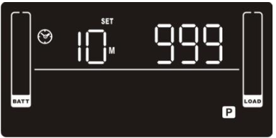
Setting # 10 is the number of minutes the programmable outlets will remain active for in the event of a power outage. The range is 0-999. If set to 0 they will immediately switch off.
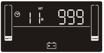
Setting # 11 is autonomy limitation. You can set this to DIS (default – the unit will keep going until the batteries become too low), or from 0 (in fact 10 seconds) to 999 minutes. This is useful particularly if you have a very low load and don’t want the batteries to deplete to a critical point and may only needs a few hours runtime.
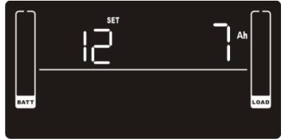
Setting#12 is the connected battery Ah of the UPS from 7-999Ah. If you have a single UPS then this value will (depending on model) be the internal battery Ah so either 7 or 9Ah. Remember if you add further batteries to the UPS (e.g. additional battery cabinets) to add the additional Ah here. For example a VFI1500RT+ has an internal 9Ah battery, so this should be set to 9Ah. If we add 5 cabinets to it, each with a capacity of 18Ah, then we should set this value to 99. (5x18Ah for the cabinets plus 9Ah for the internal).
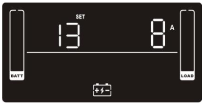
Setting #13 is the battery charger current. One of the great features of the VFI-RT+ is the ability to extend runtime by the addition of external battery cabinets or even large battery strings. However this additional battery capacity needs a more powerful charger to recharge the system. Luckily the VFI-RT+ has an adjustable battery current up to either 8A or 12A dependent on your model. Options are 1/2/4/6/8 or 1,2,4,6,8,10,12. The default is 2A. You should not set the charge current to a high value with no additional battery cabs connected.
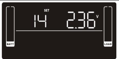
Setting #14 is the charger boost voltage. You can adjust this but this is inadvised. To do so may damage batteries.
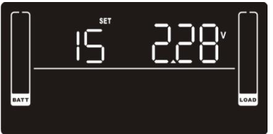
Setting #15 is the charger float voltage. Again you can adjust this but this is inadvised.
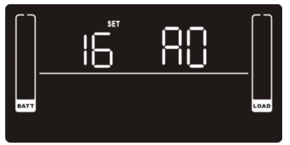
Setting #16 is the Emergency Power Off (EPO) ports control logic. You can set this to AO (Active open) or AC (Active closed).
AO is default, and therefore requires the EPO connector at the rear of the unit to be linked through and present. If you want to remove it or work on a different logic then you can do so by setting the logic here.
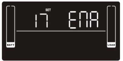
Setting # 17 is for when an external isolation transformer is connected to the output of the UPS. If enabled the unit will attempt to compensate for transformer regulation by adjusting the output voltage depending upon the load power being drawn. E.g. the voltage at low power draw will be lower than at high power draw. It is disabled by default.
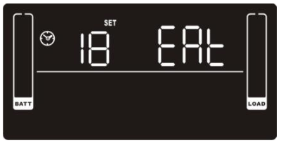
Setting #18 is a preference for how to display autonomy when the unit is running on battery. Options are either EAT (default) or RAT. EAT will display how much autonomy time the VFI-RT+ thinks you have left based on the connected battery Ah, the current load and battery capacity. RAT will display how much autonomy time has been accumulated already.
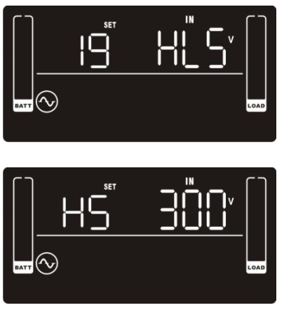
Setting #19 defines the acceptable high points and low points before the unit will revert to battery power. The options are from 110/120/130/140/150/160 (default 110) to 280/290/300 (default 300).
The purpose for this is really on the low voltage side, since if you are supplying a fixed KW output then the UPS will draw as much power as required from the input to maintain the output voltage and power. This could potentially mean overloading a circuit if it susceptible to brownouts. (A system at 240V will draw half as much current as a system at 120V for the same power for example)
That’s It!
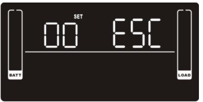
And finally we are here. Press OFF/ENTER ↲ to accept all the settings. The UPS will then revert back to standby with all the settings enabled and you can now switch it on.
If you made a mistake don’t press the OFF/ENTER ↲ key, just wait a minute or so and the system will time out and come out of the menu. Or you could just switch off the mains power.