A line interactive Uninterruptible Power Supply is characterised by its ability to raise the input voltage when it is too low, and to lower the input voltage when it is too high. This provides a degree of voltage regulation. This process is sometimes known as Automatic Voltage Regulation or AVR, however some manufacturers of AVR equipment may – and probably do – object to this as a line interactive UPS is a very loose AVR whereas a dedicated AVR device offers tight control on output voltages. A better description for a line interactive UPS System would be a “buck and boost” device.
Here in this article I’m going to try and explain what one of our UPS does and for this I’m going to take the VIS2000B, apply varying voltage to it and observe the unit response. The VIS2000B is a good choice as the LCD display lets us know both input and output voltage so we don’t need to add any multimeters to the circuit. We’re going to modify the input voltage by means of a variable transformer, or a Variac. If you’re trying this at home don’t use a dimmer switch as these work in a different way.
Firstly we set the variac to nominal voltage, connect to the VIS2000B and switch it on. The display shows input voltage on the left at 230V and the output voltage on the right at 230V.
This is normal operation and so what comes in, goes out. What we will do now is increase the input voltage and observe.
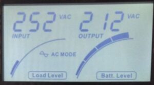
As the voltage is increased the output voltage matches the input voltage until the buck trigger threshold is reached. This is set to be around the maximum voltage that the utility should provide which is 230 +10% = 253V.
In our case at 252V the unit enters buck mode and reduces the high input voltage to 212V. [Also note that on VIS2000B the AC Mode indicator blinks.]
The lower threshold of voltage supplied by the utility is open to some debate. It is 230V -10% = 207V in much of Europe and was supposed to be the same in the UK. However the implementation date of about 8 years ago has come and gone and so officially in the UK the voltage is still set to be 230V – 6% = 216V. However other standards for products that are CE marked generally require equipment to be able to operate across the full spectrum of nominal voltages, so the output is aimed to be regulated within the realm of the EU, so 230±10% or 207V to 253V.
Raising our test variac to as high as it could go saw the unit maintain in buck mode with the output voltage rising proportionally with the input. In buck mode the input voltage is reduced by a nominal 16% or so.
Raising the input voltage even higher results in the unit disabling buck mode and reverting to battery operation.
As we reduce the input voltage the buck will at some point be deactivated and the unit will return to normal. There must be some hysteresis built into this or the unit would “chatter” eg switch constantly in and out at the threshold voltage.
In our test with the unit output reaching 207V a further reduction in input voltage caused the unit to switch out of buck mode and back into normal mode.
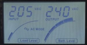
With the mains input voltage reduced further the output voltage tracks the input voltage until the boost threshold is reached at around the 207V mark.
Here the mains input is raised by around 17-18% in order to maintain the voltage within the nominal range.
Further reductions in the input voltage will keep the unit in boost mode until the output voltage can no longer be maintained within tolerance and the unit will revert to battery operation.
Raising the voltage the unit comes out of battery mode, straight into boost which then is disabled when the input voltage reaches around 211V.
To summarise, a line interactive unit attempts to maintain the output voltage within regulated limits for as long as possible without dropping to battery power. This is an advantage of over offline UPS systems that will have no option but to drop to battery instead of providing regulation, which would resort in lost loads due to UPS switching off due to depleted battery, or diminished battery life if the unit is regularly switching in and out of battery mode. However, they do not provide tight output voltage control. To achieve this online double conversion UPS systems provide a constant fixed output voltage regardless of the input voltage level.
Additional Notes with regard to the VIS2000B
One of the drawbacks of UPS Systems is the need for them to prevent a build up of heat and so many are fitted with forced cooling fans. In our VIS2000B the unit fan activates when the unit is “active” that is, on battery but also when it is in buck or boost mode. Users may find their unit enters buck mode when their mains is around the 250V mark as this will be activated should the mains hit 252V even momentarily. Due to the hysteresis effects the fan will not be disabled until the lower threshold is reached which is around the 246V mark. If this occurs, briefly switching the unit onto battery power will clear the hysteresis effect.
Note that we can change the threshold somewhat to effectively shift the buck and boost points higher by around 10V or so. This prevents the unit entering a nuisance buck mode and also makes the minimum output voltage more within the current UK spec but this does mean that the unit will allow voltages of 260+V through, should these be encountered. This is a factory setting that the Power Inspired technicians would be happy to undertake for you if required.