Telecare describes a range of products that are designed to monitor vulnerable or otherwise at risk persons to help them live more independently and safely. Where some products are designed to emit local alarms, others are connected to a monitoring service. This connection is often done over the users landline. With the digitisation of the PTSN network by 2027, ISPs and Telecare providers now have the responsibility to ensure that such users still have access to their services when their existing landline goes digital and so require Telecare Battery Backup Solutions.
What’s the problem?
In a PTSN network the telephone line is a copper wire connected directly to the telephone exchange (via a few street cabs). The telephone exchange contains chargers and large battery strings to ensure that even in the event of a utility power failure, that all devices connected to the PTSN network can operate. E.g., if you have a power cut you can still make telephone calls, activate your help cord or personal alarm and get help when you need it.
OFCOM have already provided guidance to VOIP providers that they should provide a 1hr service availability, and the UK government has recently written to a number of providers asking them to consider 8 hour solutions. Consensus appears to be a 4hr solution may be required in future.
Telecare Battery Backup Solutions
The Power Inspired iPowers are DC-DC systems that simply plug in to the DC port on the equipment to be protected. Backup times of one hour can be met with most products whereas the iPower-DC2 is suitable for 4 and 8 hour solutions for systems depending on average power consumption. To extend available backup time for Telecare equipment we suggest powering each separate device from a different iPower.
Another option is to use AC battery backup and protect all Telecare equipment including other essential equipment for in the home. The PF unit can provide pure sinewave output whilst on battery. The large Lithium battery will ensure that even runtimes of 8 hours are easily achievable for constant loads under 100W or so. In addition, the unit can be connected to solar panels prolonging the available runtime or even achieving total grid independence.
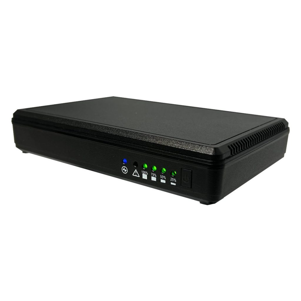
Power Inspired have complemented their range of DC UPS for broadband applications with the launch of the iPower-Mini. The small unobtrusive device sits between your existing DC power supply and the load to provide typically well over an hour of backup. This allows access to telecommunications for vulnerable people especially important these days as landline calls are now being phased out.
The iPower-Mini sits between the existing power supply and the router providing well over an hours backup for the vast majority of devices. It starts up automagically when power is applied and autosenses 9 or 12V. Simple 3 LED system gives indication of 9 or 12V output, charge / discharge status and battery low.
The unit features an auto-sense 9V or 12V output and an impressive 24W capacity. It contains a dual 3.7V 2500mAh 18650 battery (18.5Wh) giving over 30 minutes at full load (24W) and well over an hour 1 at 12W. A typical 12W 1A router should see backup times in excessive of 2 hours.
Which iPower Do I need?
Power Inspired have 3 iPower models in their range, all contains certified Lithium batteries with full protection circuitry.
iPower-H
The iPower-H replaces the existing power supply providing an extremely simple solution for 12V 1A applications.
The internal 12.4Wh battery provides typically 1hr backup. The unit is fitted with a 2m lead to allow connections that need not be directly adjacent to the load. In addition to which the sprung connector makes it suitable for both 2.1mm and 2.5mm input jacks.
The iPower-H is simple in operation with auto-start, cold-start and a single LED giving device status – ready (solid Green), charging (slow flashing Green), discharging/low battery (quick flashing Green) and fault (Red).
The iPower-H is ideal for bundling with the device to be protected saving on the cost of purchasing the power supply. The unit also contains built in AC surge diverters for added power protection.
Unlike the other iPower models the iPower-H can have the battery replaced without opening the unit.
iPower-Mini
The iPower-Mini is ideal where you have an existing power supply and you need to add backup for a single 9V or 12V application.
The internal 18.5Wh battery gives typically 2hrs backup for a 12V 1A router.
Simple to use simply plug the existing power supply into the iPower-Mini and the output lead into the device to be protected. The unit is designed to sit adjacent to the load being protected and can be wall mounted via the rear keyhole slot.
The three LEDs give indication of set voltage (Red for 9V and Green for 12V) if the unit is running on battery power (Orange LED) and if the battery is running low (flashing orange). The charge indicator (Green) flashes when charging and is solid to indicate fully charged.
Due to the auto-sense function the iPower-Mini cannot be cold started.
iPower-DC2
The iPower-DC2 is a selectable 9V/12V or 24V system with a huge 30W capacity making it suitable for powering multiple devices, including USB powered.
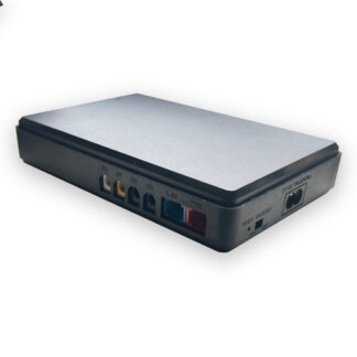
It can be utilised with an existing power supply or bundled with a suitable device (typically bundled with a 12V 3A PSU) and allows battery backup protection for both the ONTs and the hub in a typical fibre broadband installation.
Various output cables can be provided to match the individual installer requirements, with the unit either sitting on a shelf or alternatively DIN rail mounted using an optional accessory.
The large 37Wh battery provides many hours backup for the majority of devices – the 1hr regulatory requirement is met at 25W.
Front LEDS give indication of set voltage (Red / Blue or Purple) and 4 Green LEDS show battery charge / discharge status.
There are 5 output DC jacks and a USB port for connection of multiple devices.
The iPower-DC2 auto starts and can be cold started (since the output voltage is manually set).
Unlike applications where sudden power loss causes data loss or other operational issues, power loss to a pharmacy fridge is not such of an issue since the internal temperature is well controlled. In the event of a power cut a solution is simply not to open the fridge. A typical fridge will maintain the internal temperature for around 4 hours in the event of a power cut – provided the door is unopened. However note if the fridge cannot be opened then no medicine in the fridge can be retrieved.
Many laboratory or pharmacy fridges have alarm contacts which can alert to the fact that power has failed and as a result warn users not to open the door. However, a power fail alarm will have to be operated on a secondary power system, such as a battery, due to the obvious fact that a mains powered system would also be rendered inactive during a power outage. Having a battery system, will also require the battery to be maintained in a state of charge. These added complications mean that such alarms are rarely, if ever, implemented.
A pharmacy fridge will be used to house items, typically vaccines, diluents, immunoglobulins and other medicines with temperature requirements. The costs of these medicines can be quite substantial and if the temperature inside the fridge should rise to over +8°C, then, according to the NHS Green Book, the “cold chain” has been broken and these medicines may need to be destroyed. If not destroyed, then a time-consuming process needs to be instigated to determine the effect on the medicine which most likely will include a reduction in the expiry date.
Clearly, protection against sustained power outages has operational and financial benefits.
Fridge Power Consumption
Instead of giving power ratings of the Pharmacy Fridge, the manufacturers specify the energy consumption in KW for a 24 hour period. The method I found for doing this is here: ENERGY STAR® Program Requirements Product Specification for Laboratory Grade Refrigerators and Freezers, and Ultra-Low Temperature Freezers. This value varies from product to product and depends upon a number of factors, including capacity, the type of doors (glass or solid etc.) and the configuration (bench top, under counter etc.). Typically these figures are around 1KW/24 hour for a typical small system in a typical pharmacy. See Note 1.
The test schedule includes opening the fridge door for a period of 15 seconds (plus an additional 4 seconds for opening and closing), 3 times an hour each hour for 8 consecutive hours. This is useful as it allows us to specify a UPS runtime that will allow a degree of use of the fridge during an extended outage.
A typical fridge compressor has a power draw of around 200W, and will require a sine-wave inverter to ensure correct operation.
UPS Selection
In the table below I’ve created a lookup for the number of hours of runtime you could expect (and remember this includes periodically opening the door) given the energy rating of the pharmacy fridge.
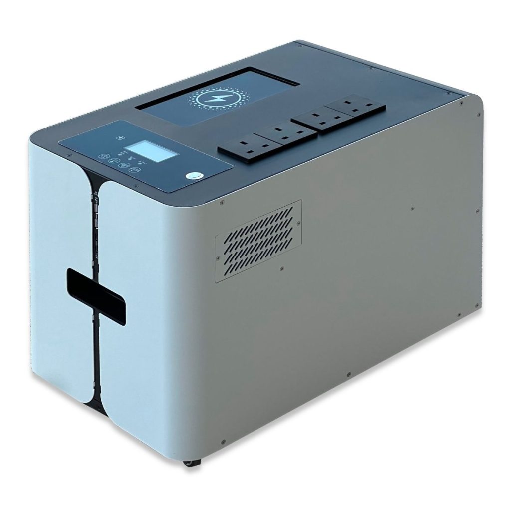
The PF-S-Li products are units ideal for Pharma Fridge applications. The units contain an internal high capacity Lithium Ion battery offering long runtimes, long life and low weight. The PF1200S-Li has a continuous power rating of 1200W, but with a surge rating of 2400W. This allows it to easily deal with the inrush current generated by the compressors of the fridges.
Achievable Runtime in hours:
Energy Rating (KWhr/24hr)
Equivalent Watts
PF1200Li Expected Runtime
0.5
21
>24 hrs
0.75
32
21 hrs
1
42
16 hrs
1.5
63
10 hrs
2
84
8hrs
2.5
105
6hrs
3
125
5hrs
3.5
146
4hrs
4
167
4hrs
4.5
188
3hrs
5
209
3hrs
Contact us to enquire about UPS for Pharma Fridge Applications.
The PF1200S-Li has superb surge rating of twice its capacity for 5 seconds allowing it to cope with the inrush demands of high performance refrigeration units. It also has the benefit of fast recharge and can be connected to a solar panel array. Connectivity is via 4xUK socket outlets and it even boasts a wireless charging pad, USB A and USB C outlets. In addition to powering the fridge it can also provide battery backed power for ancillary devices.
Note 1: I’ve used what manufacturers are displaying on their spec sheets in order to avoid confusion, however the correct term should in fact be kilowatt hours per 24 hour period eg. kWh/24
Power Inspired launch the iPower-DC2 – a DC UPS designed to provide long runtimes on telecommunications equipment. Not only will this keep equipment going in mission critical applications following a power outage – it allows FTTP (Fibre To The Premises) companies to have compliance with OFCOM guidance on providing telephony services for an hour following a power outage. 1
The Power Inspired existing iPower-H is a fantastic solution for this, and indeed is used in many thousands of installations for that very purpose, however with the increased power demands of routers and hubs the need for a more powerful and higher runtime unit became apparent.
Most DC based IT products are 12V, however a proportion are 9V powered and some even 24V. Furthermore, more essential equipment is being powered via USB. In addition several separate boxes can be required in an installation requiring several connections. The iPower-DC2 encompasses all these scenarios with adjustable 9V, 12V or 24V operation, a 2A USB port and 5 DC jack outlets. An adapter can also be used for affixing to a DIN rail on the wall or in a cabinet.
Runtime is impressive with a 10,000mAh Lithium Ion battery pack delivering over an hours runtime at 25W. Full safety is ensured by using UN38.3 certified cells, and with full battery protection circuitry – the battery pack is monitored for overcharge, over-discharge and over-current.
Operation is simple. Set the Voltage Selector switch to the nominal voltage of your power supply and plug in. The iPower-DC2 will start automatically and provide continuous power to the connected loads. If the DC power is unavailable the iPower-DC2 can be cold started – to basically act as a power bank.
To save needless expense and waste, the iPower-DC2 is intended to be used with the AC/DC adapter that comes with the equipment to be protected. However it can be provided with a suitable AC adapter within the same box and any additional leads required. It comes as standard with two 30cm DC-DC leads with sprung connectors suitable for 2.1 or 2.5mm input jacks.
Battery Life or “design life” of a battery is based on average use at room temperature (20-25°C) operation. For a modest UPS System, the design life is typically 5 years. Since, UPS applications are standby applications, the batteries are float charged, and the life is also referred to as “float life”.
The moist gel interior of VRLA batteries dries up over time, gradually reducing the effectiveness until the battery capacity is no longer viable for the application. This is why batteries will wear out regardless of how well they are maintained.
Typically, you have around 200 charge/discharge cycles in a 5 year design life battery. This is because the charge and discharge process involves a chemical reaction and this causes corrosion within the battery itself.
As this limit is approached the battery capacity starts to tail off, and can become very low very quickly. You can see that if a battery is used daily for example, the life expectancy is lower than one year.
Note how cycle life can be extended significantly by reducing the battery depth of discharge
Sulphation
If the battery is allowed to stand unused for a prolonged period of time, lead sulphate crystals form- blocking recharge. If this happens the UPS charger is usually incapable of recharging these batteries. It is possible to sometimes recover such batteries using high charging voltages that break down the sulphate but also having a current limited charger. Temperature monitoring is also required and as such, this is beyond the scope of most UPS built in chargers.
Sulphation occurs mainly when batteries are allowed to stand in an uncharged state. This is why it is important to have your UPS charged as soon as possible after an outage.
Heat
The float life of batteries is rapidly reduced with heat, and I mean rapidly.
HIGH TEMPERATURE will reduce battery service life often quite dramatically, and in extreme cases can cause Thermal Runaway, resulting in high oxygen/hydrogen gas production and battery swelling. Batteries are irrecoverable from this condition and should be replaced.
Based on this, if the batteries are locked in a cupboard with little ventilation and temperatures allowed to build, for example to 50°C, then a 5 year float life battery would be expected to last no more than 6 months, regardless of how it has been used.
Thermal runaway results on VRLA battery
Battery Life Conclusions
A battery cannot be expected to last in excess of its design life so schedule a replacement before this.
Regular cycling of the battery will diminish its performance. If your application is for regular charge/discharge cycles then the life expectancy reduction needs to be considered.
Avoid heat build up. Ensure the UPS and batteries are well ventilated with adequate air flow though the air intakes. Ensure vents are free from a build up of dust and the UPS is not in direct sunlight.
Always recharge the batteries as soon as possible after an outage to prevent the possibility of sulphation.
Our client runs a campus environment and has been suffering from regular outages on his CCTV equipment. Throughout the campus the CCTV cameras get their power directly from the street lights. This meant that a UPS solution would not have to power just the CCTV, but the lights as well.
Another problem is that space is a real issue. A competitor had visited this site and had proposed a UPS solution that would fit in a pre-fabricated cabinet outside the comms room, and this would keep the system up and running for a good 12 hours or so. Hmm, this seemed real overkill and a more cost effective solution would be to fit a small UPS within the comms cabinet and use a generator outside. This was a better solution, but not what the client wanted to pursue. Discussing this with the client it became apparent that having the system up and running for 12 hours was more of a wish list than a real requirement. In fact about an hour to 90 minutes would be acceptable. What else can we do?
The site has the street lights split into three zones, each powered from a single phase. This necessitated the use of a three phase UPS System, although the entire power consumption was in the region of 3000W or so. Our standard 10KVA 3phase UPS, the VFI33-10KT would provide around 20 minutes runtime. Not long enough.
Fitting a battery pack comprising a +/-120V strings with 36Ah capacity did the job exactly with a calculated 102 mins of runtime. There’s the solution, now where’s it going to go?
The comms room was a bit of a squeeze. And calling it a comms room is also a bit misleading. It was more of an out-house than anything. The UPS could possibly fit, but then getting in would be a challenge. As luck would have it another outhouse was nearby that we could wire the UPS to. Bring on the electricians.
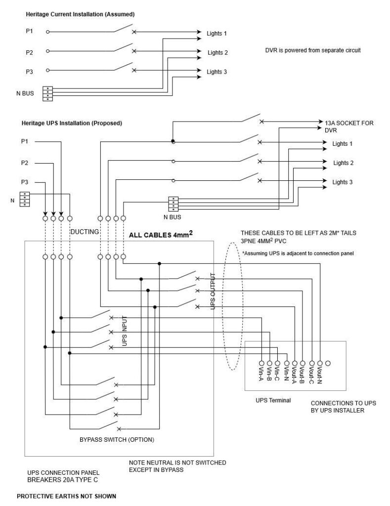
A schematic was made up, discussed with the site electrician and a plan put in place to minimise downtime. Phase 1, the electrician would run cables to the outhouse and fit the UPS input and output breaker panels. Phase 2, UPS installation, leaving it in bypass mode. Phase 3 involved unavoidable downtime where the power feeds to the cameras needed to be diverted to the UPS.
Once this was completed, the UPS internal bypass made sure that power was still being presented to the CCTV. All that was left was for Power Inspired to come back to site and commission the UPS System. Take it out of bypass and switch it online. All completed without any downtime.
Happy days, over 90minutes autonomy for a CCTV UPS application from a 10KVA 3phase UPS System with additional battery cab.
Need any idea how long your UPS will last for? Eg How much runtime will you get out of your UPS? Then this UPS Runtime Calculator is just what you need.
You’ll need to know how much power (in Watts) your UPS is delivering. Then you’ll need to know how many battery blocks and of what Ampere Hour capacity are in your UPS.
This calculator is based upon 12V blocks only and will only accept integer values. So, if you have one single 6V battery of 12Ah capacity, then you’ll need to say it’s a 12V 6Ah battery. If the spec of your battery is not in Ampere Hours but Watt Hours, then as a very rough guide divide the Wh rating by 4 to get the Ah. If you have 7.2Ah or 8.5Ah then if you round down this will give you a minimum, and round up will give you a maximum.
Note, the calculator is approximate. There are no assumptions made on standby current consumption and inverter efficiency. These will be different for different UPS and also different at different load levels. Please just use as a guide. For example if you have an AC load of 1000W, the calculator makes no allowance for DC to AC conversion losses. This allows you to add your own. For example if your system uses 5W in standby, and has an efficiency of 90% then for a 1000W AC load, use 1000 / 0.9 + 5 = 1116W.
If your load varies over time, you’ll need to estimate the average power consumption. You’ll need to size a UPS to meet the maximum power draw expected, but calculate the runtime based upon the average power consumption.
UPS Runtime Calculator
If you want to select a UPS to meet load and runtime calculators please use the UPS Selection Tool.
If you’ve used the UPS Runtime Calculator please leave a comment or drop us a line with any ideas.
Did you know BS7671:2018 Requirements for Electrical Installations, a.k.a. The IET Wiring Regulations 18th Edition states that any socket outlet 32A and under must be protected by a Residual Current Device (RCD)?
Section 4.11.3 is the Requirements for fault protection. Subclause 4.11.3.3 entitled “Additional requirements for socket outlets and for the supply of mobile equipment for use outdoors” states:
In AC systems, additional protection by means of an RCD with a rated residual operating current not exceeding 30mA shall be provided for:
(i) socket-outlets with a rated current not exceeding 32A
BS7671:2018 Section 4.11.3.3
In other words any socket outlet that you plug anything into (basically anything powered from a 13A outlet, or up to 8KVA Systems on Commandos) must have an RCD protecting that circuit. There are exceptions to this, dwellings excepted, but only following a documented risk assessment which clearly states why an RCD would not be necessary.
Purpose of RCDs.
An RCD works differently to a miniature circuit breaker (MCB) or fuse. An MCB renders devices safe in the event of an overload, or short circuit to earth. They are rated in Amps, generally in stages from 1-32A. RCDs work by tripping on an earth leakage fault typically of 30mA. This is a fault current of up to 1000 times smaller than the MCB! RCDs are useful as certain hazards can exist in the event of a fault that will not trip an MCB. Typically this involves applications that are, or may, come into contact with water.
Earth leakage is a small current that stems from phase conductors to earth. This causes an imbalance between live and neutral and it is this imbalance that RCDs detect. If the earth leakage is high enough on an appliance due to a fault or water contact then the equipment chassis can deliver a dangerous “touch current” if a user touches it. The RCD is there to protect against this scenario. If your application has water involved, then it is very difficult for a risk assessment to justify the omission of an RCD from the electrical infrastructure unless other safety measures are taken.
Isolation Transformer
An isolation transformer, by its very nature will stop RCDs from tripping – even in the event of an earth fault. See Isolation Transformers – what you need to know for further reference on this. However this isn’t a problem. In fact, the isolation transformer can make the installation more safe than with the RCD alone. Even a device with a fault can be touched by a user without any hazard occurring. Unless – and I can’t stress this point enough – the isolation transformer has the output Neutral and Earth bonded!
N-E bonds are not there for safety, but rather for noise rejection performance by establishing a zero volt neutral-earth voltage. Isolation transformers in conjunction with UPS Systems provide a very resilient power protection solution. However, in order to ensure the system is safe, then you should not bond the N-E. Our isolated UPS systems leave the system floating, providing true isolation and an inherently safe electrical environment. If you use a N-E bonded system and no risk assessment has been carried out to determine that no RCD is necessary then this contravenes the requirements of BS7671:2018.
Decision Flowchart
Start by asking if there is a documented Risk Assessment as to why there is no need for an RCD on a socket outlet. If there is, then you’re good to go and any UPS is good for this scenario. You can use isolated (floating or N-E bonded) or non-isolated depending upon your requirements.
If there is no risk assessment in place then we check if there is an RCD fitted. If not, or unknown, then in order to provide the safest environment, the solution is a truly floating isolated UPS. Granted, if no RCD is in place, fitting any UPS does not make the situation less safe, it’s just that a floating isolated UPS does make it safe.
If there is an RCD fitted, and no risk assessment has been carried out, then you must not use any NE bonded system NOTE 1. This removes the safety aspect of the RCD.
Conclusion
According to the 2018 Wiring regulations there needs to be an RCD fitted on any sub 32A circuit. This will cause power to be removed if earth leakage of over 30mA is detected. Any standard UPS will not interfere with the operation of the RCD, however an isolated UPS will prevent the RCD from operating.
However, a floating isolated system, where Neutral and Earth are not connected provides a safe electrical environment. In situations where an RCD should be installed, for example there is water required by the application, and the electrical infrastructure is unknown (for example older installations to which RCD was not a mandatory requirement), floating isolated UPS provide the ideal solution.
An isolated UPS that is floating renders RCDs ineffective but provides enhanced safety by removing any touch current hazard.
On the other hand, a N-E bonded UPS system not only negates an RCD but does not make safe any scenario to which the RCD was required to protect against. There’s a reason for section 4.11.3.3 of BS7671 and this situation violates it.
An isolated UPS with a Neutral and Earth Bond renders RCDs ineffective and does not protect against hazards for which the RCD is intended.
NOTE 1: Unless a secondary RCD is fitted to the output of the UPS.
Many moons ago we blogged about BS8418:2010 (Installation and remote monitoring of detector-activated CCTV systems, Code of Practice) and the requirements for UPS Systems. That standard stated:
Unless the mains power supply is supplemented with a stand-by generator, an uninterruptible power supply (UPS) must be able to power the CCTV control equipment and communications devices for a minimum of 4 hours after mains power failure. Where the mains power is supplemented by a stand-by generator, the UPS needs to be capable of providing stand-by power for a minimum of 30 minutes after mains power failure (for example if the stand-by generator does not start).
The 2015 revision relaxed this somewhat, allowing for a documented threat assessment and risk analysis to determine whether a UPS is required or not. That said, it is difficult to state how any threats or risks are mitigated against a loss of power without a UPS, so the requirement for UPS Systems is likely still to remain in BS8418:2015 installations.
If a UPS is used as the “alternative power source” then this has been changed from a 4 hour requirement to a 30minute requirement when supporting control equipment and data transmission devices. However the standby power capability for the detectors and semi-wired detectors remains at 4hours.
Find a UPS Solution
Enter in your load power and how long you need the UPS to provide backup power for. The UPS Selector will identify any UPS that meet your requirements.
You can filter the selection based upon required features, by clicking the checkbox. Many models are available to by online from our webstore but contact us using the form below for specific requirements or for other products not available to purchase online.