Many moons ago we blogged about BS8418:2010 (Installation and remote monitoring of detector-activated CCTV systems, Code of Practice) and the requirements for UPS Systems. That standard stated:
Unless the mains power supply is supplemented with a stand-by generator, an uninterruptible power supply (UPS) must be able to power the CCTV control equipment and communications devices for a minimum of 4 hours after mains power failure. Where the mains power is supplemented by a stand-by generator, the UPS needs to be capable of providing stand-by power for a minimum of 30 minutes after mains power failure (for example if the stand-by generator does not start).
The 2015 revision relaxed this somewhat, allowing for a documented threat assessment and risk analysis to determine whether a UPS is required or not. That said, it is difficult to state how any threats or risks are mitigated against a loss of power without a UPS, so the requirement for UPS Systems is likely still to remain in BS8418:2015 installations.
If a UPS is used as the “alternative power source” then this has been changed from a 4 hour requirement to a 30minute requirement when supporting control equipment and data transmission devices. However the standby power capability for the detectors and semi-wired detectors remains at 4hours.
Find a UPS Solution
Enter in your load power and how long you need the UPS to provide backup power for. The UPS Selector will identify any UPS that meet your requirements.
You can filter the selection based upon required features, by clicking the checkbox. Many models are available to by online from our webstore but contact us using the form below for specific requirements or for other products not available to purchase online.
Our Lithium Ion UPS range is an impressive series of UPSs with internal Lithium Ion batteries, that make the units efficient, lightweight and more environment friendly. They also reduce the whole life costs of the UPSs. We have conducted some tests to show you how the Lithium-Ion UPS compares to the VRLA UPS in terms of runtime.
Each unit is connected to 1800W load. The Lithium UPS battery capacity is 48V 9.9Ah = 475VAh. The VRLA UPS battery capacity is 72V 9Ah = 648VAh. Although the Lithium UPS has only 75% of VRLA UPSs battery capacity, the runtime results are outstanding! See the video below:
We provide 5-year warranty on the Lithium-Ion UPS systems including the batteries.
Lithium-Ion UPS only from Power Inspired. Learn more at www.lithium-ups.com and register your interest.
The definition of transfer time, sometimes also called switchover time, says it is the amount of time a UPS will take to switch from utility to battery supply during a mains failure, or from battery to mains when normal power is restored. What this means is that when the main power supply fails, the UPS will need to switch to a battery mode to provide sufficient power and ensure smooth running of the attached equipment. The transfer time duration differs, depending upon the UPS system attached. It should, however, always be shorter than your equipment’s hold up time. Hold up time is the amount of time your equipment is able to maintain consistent output voltage during a mains power shortage.
Line interactive UPS systems, such as our VIX or VIS series, have transfer time typically between 2-6 milliseconds. For regular computer based systems, where hold up time is approx. 5 milliseconds, line interactive UPS systems are usually sufficient; however some computer systems, as well as other critical sensitive equipment, are more sensitive and require shorter transfer time. Hence in this case you should always choose UPS with zero transfer time like our VFI series.
If your equipment is critical and doesn’t tolerate even slightest power distortion, we recommend choosing online double conversion UPS technology with zero transfer time to ensure your equipment has the highest degree of protection.
Here’s a quick look up of transfer times for Power Inspired UPS systems:
Product
UPS technology
Typical transfer time
VIX3065
Line interactive UPS
Typically 2-6 milliseconds
VIX1000N
Line interactive UPS
Typically 2-6 milliseconds
VIX2150
Line interactive UPS
Typically 2-6 milliseconds
VIX2000N
Line interactive UPS
Typically 2-6 milliseconds
VIS1000B
Line interactive UPS with sinewave inverter
Typically 2-6 milliseconds
VIS2000B
Line interactive UPS with sinewave inverter
Typically 2-6 milliseconds
VFI1500B
Online double conversion UPS
Line to battery
0 milliseconds
Line to bypass
Approx. 4 milliseconds
VFI3000B
Online double conversion UPS
Line to battery
0 milliseconds
Line to bypass
Approx. 4 milliseconds
VFI3000BL
Online double conversion UPS
Line to battery*
0 milliseconds
Line to bypass
Approx. 4 milliseconds
VFI6000BL
Online double conversion UPS
Line to battery*
0 milliseconds
Line to bypass
Approx. 4 milliseconds
VFI10KBL
Online double conversion UPS
Line to battery*
0 milliseconds
Line to bypass
Approx. 4 milliseconds
VFI1000T
Online double conversion UPS
Line to battery
0 milliseconds
Line to bypass
Approx. 4 milliseconds
VFI3000T
Online double conversion UPS
Line to battery
0 milliseconds
Line to bypass
Approx. 4 milliseconds
VFI10KT
Online double conversion UPS
Line to battery
0 milliseconds
Line to bypass
Approx. 4 milliseconds
TX1K
Online double conversion UPS with isolation transformer
Line to battery
0 milliseconds
Inverter to bypass
4 milliseconds
Inverter to ECO
Less than 10 milliseconds
TX3K
Online double conversion UPS with isolation transformer
Line to battery
0 milliseconds
Inverter to bypass
4 milliseconds
Inverter to ECO
Less than 10 milliseconds
TX6K
Online double conversion UPS with isolation transformer
Line to battery
0 milliseconds
Inverter to bypass
4 milliseconds
Inverter to ECO
Less than 10 milliseconds
TX10K
Online double conversion UPS with isolation transformer
Transfer times are dependent on which stage the power interruption occurs in. That’s why the transfer times stated in the above table are approximate.
As previously mentioned, transfer times also measure the amount of time it takes for the UPS to switch back to mains. The transfer back to mains power is always controlled with minimal interruption as this transfer is planned. As opposed to an unplanned mains failure which happens suddenly and hence a variation in the actual time taken.
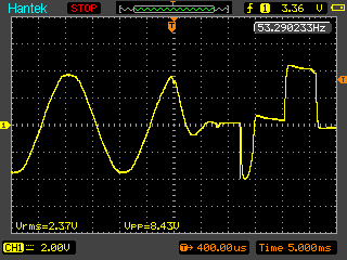
We have conducted a transfer time measurement using an oscilloscope (photograph above). For purpose of this exercise, we have used a standard line interactive UPS system and stimulated a power cut. The oscilloscope managed to capture the transfer time which on this occasion lasted 15 milliseconds, due to the original sine wave being interrupted at the peak of the cycle.
“How does transfer time affect my equipment?”
That’s simple – if your equipments tolerance is below UPS transfer time, the UPS will not provide power in sufficient time in order to keep your equipment running.
Let’s say you have highly sensitive laboratory equipment with hold up time of 2 milliseconds. Line interactive UPS will not be sufficient in this case as it will not switch to battery mode quick enough. You will need to invest in an online double conversion UPS or Isolated online double conversion UPS in order to avoid any downtime. On the other hand if your equipment is a very basic computer workstation with approximate transfer time of 10 milliseconds, you can use the line interactive UPS system with peace of mind that your equipment is protected.
Transfer time is definitely one of the things you need to keep in mind while searching for suitable UPS. More factors affecting your choice of UPS technology are covered in this article.
Electricity is mainly generated by turning a large magnet through coils of wire. This induces a clean sinusoidal waveform that can be transmitted down cables, stepped up and down using transformers, to eventually find it’s way into our homes, offices and factories. Along the way, however, some power virusescan interfere with this clean power and cause your equipment power problems. Some problems are obvious, and others not so. There’s generally accepted to be 9 power problems but there’s another problem which is often overlooked and we make it 10.
1. The Blackout
This is one of the most obvious power problems. A complete loss of power. Caused by a variety of reasons, tripped breakers, fuses blown, faults on the utility line, the list goes on. Some power cuts are brief lasting only a moment, for example lightning striking a power line causing protection equipment to operate and then reset. Some may be for hours or days, for example when a cable is dug up by accident. Others last until the breaker is reset. Whatever the cause a sudden loss of power is clearly undesirable for electrical equipment.
Oops!
Only a UPS System can protect against black outs. Your choice of UPS will depend upon the load you are protecting and the amount of time you need support for.
2. The Power Sag
Also known as a power dip, this is where the power momentarily drops. It’s usually caused by the start up of heavy electrical equipment. Other causes include overloads on the network, or utility switching. Note that the plant that is causing the power sag may not be in your building but sharing the same substation. The severity of the dip will impact equipment in different ways. Some equipment will have a natural ability to cope for momentary dips where others will shut down or reset.
You will need a UPS System to protect against a power sag.
3. The Voltage Surge
Some call it a spike, but in any event it’s a short term high voltage on the power line. Usually caused by lightning, which doesn’t have to be a direct hit on the power lines but nearby causing the spike to be induced onto them. The surges are generally destructive in nature as most equipment is not designed to protect against them.
This is where the voltage drops below 10% of the nominal voltage for an extended period of time. This is caused by high demand on the network. The effect is more pronounced the further you are away from the electrical substation. In fact, in rural areas this can be a problem when switching on everyday appliances such as ovens or electric showers. Brown outs affect different equipment in different ways. Computer systems tend to be able to cope well with brown outs as the switch mode power supplies have a wider input voltage. Other equipment that relies on a stable AC source such as lighting, motors or heating will not fare so well. Equipment with linear power supplies such as in high end AV applications may fail entirely.
In order to protect against a brown out you will need some form of voltage regulation. A line interactive UPS System incorporates a boost function to raise the voltage higher by a fixed percentage to bring it into the nominal range. It does this without needing to revert to battery operation.
5. Over Voltage
Also known as a voltage swell this power problem is caused when the demand on the network is lower than normal. This causes the output voltage from the substation to rise. This is a problem when the voltage is over 10% of the nominal. The effects of over voltage can range from overheating, diminished equipment life to complete equipment failure. It’s the inverse of the brown out in that the closer you are to the substation the more pronounced the effect will be.
Similar to the brown out you will need some form of voltage regulation. A line interactive UPS System incorporates a buck function to lower the voltage by a fixed percentage to bring it back into the nominal range.
6. Electrical Noise
This is generally noise between the live and neutral conductors and is called normal mode noise. Its caused by radio frequency interference (RFI) or electro-magnetic interference (EMI). This is usually from electronic devices with high switching speeds. Since the noise carries little energy it generally does not cause damage but rather disruption in the function of other electronic systems. Some filters may remove this, but this is not always effective. The best way to eliminate noise is to recreate the output waveform and this can only be done with an online double conversion UPS System.
7. Frequency Variation
Frequency variation can’t occur on the utility as this would require all the power stations in the country to suddenly change frequency. In fact, the frequency on the national grade is very tightly maintained at 50Hz. However, when you’re not connected to the utility and instead relying on a portable (or even large scale) generator then this can be an issue. As the load increases on the generator and in particular sudden large power draws from them causes the motor to slow down and hence change the output frequency. Some equipment won’t be affected by this at all but it can cause damage to other systems, particularly those with motors or other inductive devices.
More severe than electrical noise, switching transients are very fast high voltage spikes induced onto the power conductors. Caused by the switching off of inductive loads and variable speed drive systems. Such power problems may not be immediately damaging but they can cause degradation of devices subjected to them, particularly if the transient is of high enough voltage.
A surge suppressor can help if the magnitude of the transient is high enough, but these only work at levels above the nominal voltage. This means you could still have a transient of many hundreds of volts entering your equipment. Like with electrical noise a filter will help, but can only reduce a transient not eliminate it. The only way to be sure to eliminate the transient is with the online double conversion UPS System.
9. Harmonic Distortion
Harmonic distortion is where the supply voltage varies from a pure sine wave. The amount of variation is a measurement called the Total Harmonic Distortion or THD. Since we’re talking about voltage we call it THDv, not to be confused with THDi which is a measure of the distortion of input current which is a different thing entirely.
It is generally caused by non-linear loads. These are types of loads that don’t take current in a smooth sinusoidal fashion but instead take it in large chunks. Depending on supply characteristics these chunks of current cause a greater or lesser degree of distortion on the supply voltage. This causes problems for motors and transformers with hum and overheating. In three phase supplies harmonic distortion can actually cause the burning out of neutral conductors and surprise tripping of circuit breakers. Again the only way to eliminate harmonic distortion from your load is to use the online double conversion UPS System.
Summary
That’s the main generally accepted 9 power problems that can cause issues for electrical and electronic equipment. But wait, didn’t I say there was a tenth?
10. Common Mode Noise
This power problem is often overlooked and can cause equipment malfunction. It’s defined as electrical noise between the earth conductor and the live/neutral conductors. Even an online UPS System may not eliminate common mode noise. This is because it is normal practice to have the neutral conductor connected through the UPS from input to output. So although any noise between the live conductor and ground would be taken care of, any noise between neutral and ground is passed straight through to the load.
In a modern electrical infrastructure this generally may not be a problem since the neutral and earth are tied together at the distribution board. This shorts them together and in theory eliminates any voltage or noise between them. However, particularly on long circuits with a lot of equipment on them, voltages can start to be created and common mode noise becomes an issue. Hospital laboratories are a prime example of this.
The way to solve common mode power problems is to isolate the load from the supply. This is exactly what the TX Series does. The in-built isolation transformer creates a new live and neutral, and the online double conversion technology then ensures a high quality stable output. An an added advantage the isolation transformer can provide a safety shield against electric shock which is particularly important in applications where water and electricity may mix. Again, hospital laboratories are a prime candidate. Thus the TX Series can also be defined as Laboratory UPS System. Click for further information on the isolation transformer.
The new summary is this. If you need to provide the highest degrees of power protection against power problems and viruses then the UPS Technology choice should be online double conversion, and the load should be isolated. Choose the TX Series Isolated UPS System.
For the highest degrees of power protection the TX Series of Isolated UPS from 1-10KVA
Did you know that majority of UPS’s trouble shootings are battery related? Typical life span of UPS internal batteries ranges from 3 to 5 years; however this depends on numerous factors. Here are a few easy tips to ensure that you get the most out of your batteries and therefore your UPS system:
Selecting the correct UPS technology:
Uninterruptible Power Supply systems operate in battery mode in two major situations: if the power goes off, or if the mains power input goes out of tolerance. This could mean for example too low or too high voltage, or frequency anomaly (e.g. running off a generator). Some UPS technologies can provide wider input voltage and/or frequency window, which resolves this issue. Example of such technology is online UPS technology – for example our VFI series. Selecting the correct UPS technology for your equipment will ensure the UPS only works off battery in case of emergency. This will prolong the battery’s lifetime.
Positioning of UPS:
While installing your UPS be sure to take into account the following factors: your Uninterruptible Power Supply system should be positioned in temperature stable, dry environment. Position your unit so that all ventilations and fans are clear to prevent overheating. The environment should be clean and dry, with no excessive dust or corrosive fumes. If you require the UPS system to be located outdoors, use appropriate storing cabinet – for example our Willo. Small cupboards or other enclosed spaces other than the ones specifically designed for such purposes with ventilations and cooling technologies are not suitable for storing your UPS system.
Temperature:
Although specifications for Uninterruptible Power Supply systems usually state temperature between 0°-40°C, it is ideal to keep the ambient temperature between 20 °– 25°C. This will ensure that the UPS will function properly and the battery won’t deplete due to the heat. High temperature drastically reduces battery life – essentially for each 10°C over 30°C, battery life halves. In extreme cases the batteries may start swelling due to a thermal runaway. To prolong battery life, aim to keep your UPS system in an environment with temperature between 20°-25°C.
Use of UPS:
The way you use your UPS can have a huge effect on your UPS’s battery life. We recommend that during a power cut you never leave your UPS battery to completely deplete to 0%. Power cuts are usually momentary in which case you don’t need to worry about this, but if you suffer from frequent and prolonged power outage, you should take the time to switch off your equipment and then turn off the UPS to ensure that the batteries don’t deplete completely if possible. Please note that batteries only have so many charge-discharge cycles which are higher the less the battery is discharged. If you don’t discharge to zero you will get more cycles out of your batteries.
Storing UPS:
Should your UPS not be in use for a long period of time, we strongly recommend to charge the batteries before storage. Never leave a UPS disconnected from mains for a long period in a discharged state.
Service:
A battery service after few years of use is a necessity to ensure that your UPS is functioning correctly. For more information read our previous blog post about our UPS battery services.
This article looks at GPON ONT UPS solutions, why you need them and what the solution is. GPON is the acronym for Gigabit Passive Optical Network and is used in “last mile” broadband distribution to provide “Fibre To The Home” or FTTH. Once in your home, the fibre is terminated with an Optical Network Termination device or ONT. If you want to read more about this then try this GPON Fundamentals, but seriously you don’t have to.
What GPON allows is seriously fast broadband into your home but there is a drawback – and it’s nothing to do with broadband, it’s to do with power.
In a typical broadband connection you have copper wires coming into your house. These wires carry a 50V supply which originates from the telephone exchange. This allows the ability to make (and receive) landline calls from your telephone service during a power outage. Essential during any emergency.
GPON however uses fibre optic cables. These cables are made from glass, and glass if you didn’t know is a very bad conductor of electricity (in fact a very good insulator) and so it is impossible to deliver power from the telephone exchange to your home or office. Of course, the result of this is that in the event of a power outage you are unable to make or receive any landline calls.
Depending upon circumstances this may not be too much of an issue. Mobile devices have largely removed the need for landline telephones, however in areas of poor signal quality the need for a landline is paramount.
What’s more, services such as Skype, FaceTime, WhatsApp etc., will also fail as the GPON ONT will be without power and therefore your home or office without internet connection. As well as the fact that you would have to deal with restless children not being able to play on their tablet devices, workers twiddling thumbs etc., there is a more serious note in that you may be completely cut off from any form of communications.
An Uninterruptible Power Supply can provide back up power for just such an eventuality, and for 12V supplied ONTs the iPower is the ideal GPON ONT UPS solution. The iPower has a 12V 2.1A output and in most cases will replace the supplied power supply that came with your ONT. This means that the unit occupies no additional space and simply plugs into your device.
The iPower can provide up to an hour or more back up, depending upon the power requirements of the ONT, enough to protect against the majority of power cuts, or allow you to make an important emergency call in the event of something more serious. For longer runtimes the iPower-HD (coming soon) can provide hours if not days of runtime, or a standard AC system may suffice.
An isolation transformer is a transformer used to transfer electrical power from a source of alternating current power to some equipment or device while isolating the powered device from the power source, usually for safety reasons. Isolation transformers provide galvanic isolation and are used to protect against electric shock, to suppress electrical noise in sensitive devices, or to transfer power between two circuits which must not be connected. A transformer sold for isolation is often built with special insulation between primary and secondary, and is specified to withstand a high voltage between windings.
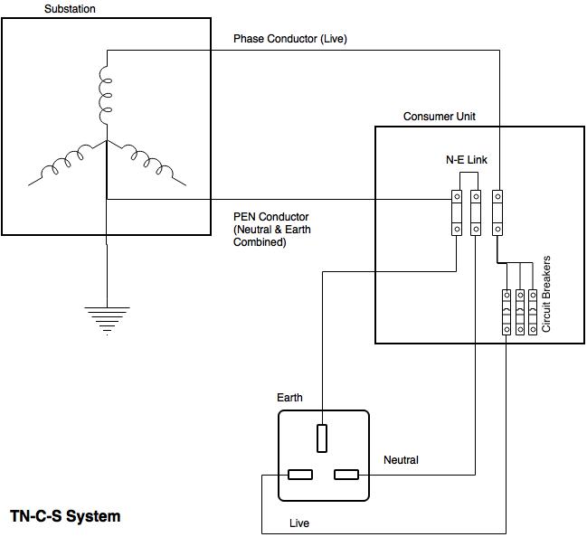
You probably don’t know it, but your mains supply is most likely provided to you via an isolation transformer. In the electrical substation that feeds your home lurks a huge chunk of copper and iron (the transformer) that takes relatively high voltage electrical power and converts this to our recognised 230-240V voltage that we all know. Your home is supplied with a cable from this transformer that has two conductors. One is the live conductor, and the other is a combined protective earth and neutral (PEN) conductor. (This is known as a TN-C-S system which is the most common in the UK. Other systems are available.)
Once inside your house, the PEN conductor is separated into neutral and earth inside your consumer unit / distribution board aka fuse board. Note that here, the neutral and earth are bonded together which means that the voltage from live to neutral is the same as live to earth – a nominal 230V, and the voltage from neutral to earth is zero (as they are bonded together). Also note that the live conductor via the electricity board fuse, is split into feeds for your different circuits each protected with a circuit breaker or fuse. For extra protection a residual current device (RCD) may also be fitted. Whereas a fuse or circuit breaker will generally require many amps of current to trip or blow an RCD trips with around 30mA of current flow to earth (actually an imbalance between the live and neutral currents which in normal operation are the same). It is used to provide extra protection when contact with water may be experienced, or other potentially hazardous situations. Remember this!
The idea behind this arrangement is for electrical safety. Should a live conductor become detached from inside a piece of equipment and touch the earthed chassis then a high current will flow and blow the fuse or trip the breaker. The same result will be obtained if the equipment should develop a short circuit between live and neutral. If an electric shower has an exposed conductor that water comes in contact with, then there will be a smaller electrical current that will flow from live to earth and this is detected by the RCD which will trip and remove electrical power to the faulty piece of equipment (and everything else on the same circuit). Handy if you’re naked in an earthed bath.
So now we have three conductors at our wall outlet. Assuming we are connected to earth (as we are standing on it), then we will receive an electric shock if we happen to come into contact with the live conductor, but we will be safe if we touch the neutral conductor (as Neutral to earth voltage is zero). If we’re isolated from earth (eg with rubber boots) then we could touch the live conductor and not receive a shock. If we touch both the live and neutral conductors then we will get a shock of course.
The Isolation Transformer for Safety
So how can the isolation transformer be used for electrical safety? It all comes down to what a transformer actually is. In the simplest terms it is two coils of wire around an iron core. The incoming coil – called the primary – converts an electric field into a magnetic one. This magnetic field then induces an electric field on the second coil and hence a voltage appears on the output of this coil (called the secondary). By varying the number of turns in the coils the voltage can be stepped up or down, but in our case the number of turns are equal and so the output voltage is the same as the input voltage. However, the point to grasp here is that there is no electrical connection between the input and the output. The link is done by magnetism. This means that the output is “isolated” from the input and hence the term isolation transformer!
The output of the isolation transformer still has a nominal output voltage of 230V between its output conductors, but there is no link to earth. This means that you can safely touch either conductor without risk of electric shock. You will still get an electric shock if you touch both conductors however!
It is important to note that with an isolation transformer, a device that may have an earth fault that would trip a circuit breaker or blow a fuse will work just fine. In fact, isolation transformers are used for this very reason in certain applications where the sudden disconnection of power due to an earth fault may cause even larger hazards (such as in chemical plants, or in operating theaters). In such cases monitoring is usually provided so that an alarm is raised should this occur.
In the diagram above, taking an installation without an isolation transformer, the device has an earth fault (for example a live conductor has shorted to the chassis). Since Neutral and Earth are bonded in the consumer unit the system sees this as a short circuit and so a large current will flow which will blow the fuse or trip a circuit breaker. It would also trip an RCD if fitted.
When an isolation transformer is put in circuit, nothing will happen. This is because the secondary live and neutral are no longer live and neutral. They really should be called phase 1 and phase 2 hence I’ve put them in quotes. Since they are no longer live and neutral there is no reference to the incoming earth, and therefore no fault current can flow. In this case since there is a fault from “live” to earth, this “live” effectively becomes the equivalent of neutral and the “neutral” effectively becomes live. In the diagram above you would have 230V between “live” and “neutral”, 230V between “neutral” and earth and zero volts between “live” and earth.
However, the main use of an isolation transformer for safety is when people are working live an accidental touch of a live conductor will not cause an electric shock, or that there is risk of damage to cables etc. such as in building sites.
Another consequence of this is that “earth leakage” that is, a trickle of current from live to earth, caused by mains filters, is eliminated. Since there is no direct earth connection, then there is nowhere for the earth leakage to flow to. This can be advantageous in patient vicinity applications or to reduce earth leakage from several devices to avoid nuisance RCD trips.
Use of the Isolation Transformer for reducing electrical noise.
The transformer, being a coil, has what is known as inductance. Inductance is a barrier to high frequency signals. Electrical noise is a high frequency signal and so the transformer acts as a block to this. Other power problems can also be reduced especially if there is an electrostatic screen in the transformer construction which is connected to earth. Any electrical transients between the power conductors and earth can be effectively reduced using this method.
Disturbances between the power conductors can be reduced by the inductance but not eliminated. This is why in dedicated power conditioning devices that incorporate isolation transformers, further filtration is placed on the secondary side of the transformer to reduce this further.
Rather than go into details about this, this piece makes for good bedtime reading.
Or you can just take my word for it.
Redoing the N-E Bond
In complex electrical installations, or some where the wiring may be old, have poor connections or otherwise has excessive impedance, the voltage between neutral and earth can increase, particularly at the furthest points from the distribution board and particularly where high currents are involved. This may, or may not be a problem for your electrical equipment. You could just rebond the neutral to earth again, but electrical codes do not allow for this. However since the secondary is isolated from the primary you can safely derive a new neutral and earth by bonding these together at the secondary of the isolation transformer. This is also done to eliminate noise between “neutral” and earth – as you are shorting it out.
There is a safety concern when doing this however. If, for example, equipment in areas that may come into contact with water (for example laboratories) it is desirous to protect this circuit with a residual current device. This is because water is a pretty poor conductor of electricity and in the event a piece of equipment becoming splashed with water not enough current would flow to blow a fuse, but enough current could flow to give somebody who may be in contact with the water and earth a nasty electric shock. Note that is only takes several milliamps of current to cause heart beat disruption.
Take the scenario above. To protect operators working on equipment with the risk of water contacting live conductors the circuit has been fitted with an RCD. Should water be spilled onto the equipment and come into contact with live conductors a leakage current will flow causing the RCD to operate. This will disconnect power from the equipment and leave the operator safe.
In the next scenario, an isolation transformer has been fitted and supplies the equipment. Should water be spilled now any contact with live conductors will only reference the conductors to earth. No current will flow and hence the operator will be safe and the equipment will continue to operate.
In the final scenario, the isolation transformer has had the earth connected to one of the secondary phases creating a new effective neutral-earth bond. Should water now be spilled on the equipment and come into contact with live conductors a current will flow from the phase end of the transformer, to the equipment, through the water to earth and then back to the transformer. Since this current path is contained within the secondary of the transformer, the RCD will not detect an imbalance and will therefore not trip. The operator is now in an unsafe environment with the potential for an electric shock as they may become the lowest point of resistance for the leakage current.
It is not only water where such hazards can exist. I recall being told of the case of an unfortunate checkout operator at a major grocery store chain. Unbeknown to her, an electrical cable feeding some equipment had become entangled in her chair mechanism. As she swivelled in the chair this caused a cut in the insulation of the cable which then contacted the live conductor. This circuit was not protected by an RCD but only by circuit breakers. It would therefore take a fault like current to trip the breaker. In this instance the chair made a poor connection to earth and so the chair – and the unfortunate operator – were now at live potential. Everytime she touched something that was earthed – such as the till or conveyer mechanism – she received an electric shock. If the circuit was protected with an RCD then this would not prevent an electric shock but the severity would be reduced and it would only happen once, rather than the multiple times it happened to this poor lady until power could be removed. The retrospective action was indeed to fit RCDs (and do this in all stores). If they were to fit an isolation transformer then the operator would not have received an electric shock at all. No fault would be apparent – save for a visual inspection. If they were to fit an isolation transformer with a N-E bond on the secondary, then this would have negated the effect of the RCD rendering another dangerous situation for the operator.
Transformer Regulation
Transformers are not perfect and impedance exists in them that causes a volt drop within the transformer when current flows. The more current that flows the larger the volt drop and so the output voltage falls. The regulation of a transformer is the difference in the no-load voltage to the full load voltage expressed as a percentage. Poor regulation can introduce other problems into a circuit. For example, if the load is non-linear and takes current in high value chunks – such as in rectifiers, then the poor regulation can cause waveform distortion and introduce voltage harmonics into the system. Other problems include the voltage falling too low and causing under-voltage protection systems to operate.
UPS and Isolation Transformers
Before I go into UPS with isolation transformers it’s probably worth mentioning what happens with transformerless UPS Systems in the event of an earth fault like described above. Earth leakage is not eradicated using a UPS. In fact it is cumulative so the earth leakage of the UPS is added to the earth leakage of the connected loads. This is a consideration for pluggable UPS but that is the subject of another article. If an earth leakage event occurs that trips the RCD then power to the UPS will be lost and the UPS will do what it is meant to do and that is continue to provide power to the connected load – even if it does have a fault. Note I’m assuming here that this is a fault in the order of tens of milliamps- enough to trip the RCD but not enough to blow a fuse or trip a circuit breaker. This you would feel is a hazard. However, when a UPS is operating from battery it will have (pluggable systems – not always the case on hardwired systems) a back-feed relay. What this does is open to prevent the output of the inverter being present on the incoming supply pins on the UPS. This is effectively the same as isolation. The load is now isolated from the source and therefore no earth leakage current will continue to flow and therefore no hazard will exist.
When a UPS has an isolation transformer this provides added power protection but it does require certain considerations. Firstly, it requires a big chunk of copper and iron to be added to it, substantially increasing its weight and physical size. As described above, the creation of a neutral-earth bond on the UPS secondary causes any RCD protection to be redundant, so it is preferable to have the transformer floating. On hardwired UPS systems, if a N-E bond is desired this can be added by the site installers quite easily and any RCD protection installed downstream of the UPS. Also, where in the UPS circuit should the transformer go? Should it be on the input or the output?
If it is on the input, then the UPS has the added benefit of the protection afforded by the transformer. It means that the earth leakage of the UPS (and connected equipment) is zero as measured on the input to the UPS. It also allows for tapped transformers on the input to allow for dual 110V / 230V input (as is done on the TX1000D).
If it is on the output, then the UPS output will always be consistent whether or not it is running from battery power or in normal operation. This would be especially important if a N-E bond is required. In addition, as in the TX10K, the transformer is on the output and has dual secondary windings allowing for both 115V and 230V output voltages. With an output transformer, earth leakage from the connected load is eliminated, but not from the UPS itself.
Edit – Floating Voltages
Adding this to the original article to explain in detail why the output voltages to earth are as they are.
If we take our isolation transformer on which the output secondaries are not connected to earth. Try as we might there will always be some parasitic capacitance between the output phases to earth, the impedance of which we will call Zp.
Then we measure, (using a high impedance voltmeter) between Phase 1 and Phase 2 and we will get the output voltage Vo. Now measuring between Phase 1 and Earth, what will we expect to find? We are measuring the voltage across the parasitic impedance Zp. Assuming this is the same between phase 1 and earth as is between phase 2 and earth, then the voltage measured will be Vm = Vo (Zp / (Zp + Zp) ), or Vm = Vo/2, eg what we measure is half the output voltage. So for a 230V transformer we would expect to measure around 115V.
If we connect a piece of equipment to the transformer that contains an input filter, then we will find there are capacitors intentionally connected between the input phases and ground. Ignoring Zp (as Zc≪Zp), then Vm = Vo(Zc/(Zc+Zc)) Eg half Vo again.
This is why the measured voltage between phase and ground tends to be around half the transformer output voltage. I can see why at first glance this may cause concern, as it appears that we have a high voltage to earth even via our isolation transformer. However no current will flow (and hence it is safe) if we make a connection between any phase and earth. All we do is now reference that phase to earth.
Lead Acid Batteries are the ubiquitous form of energy storage for Uninterruptible Power Supplies due to the high power density that can be achieved, simple charge characteristics and non-spillable operation.
In pluggable UPS systems the lead acid batteries are always maintenance free and sealed, e.g. they do not require topping up with distilled water. They are also referred to as “Gel” batteries as the electrolyte is not in liquid form.
Protection against explosion due to overcharge is incorporated by means of valves which will open if there is a build up of gas to release it. This gas is hydrogen, which is explosive and for this reason lead acid batteries should always have ventilation.
There are a distinct number of charge / discharge cycles that lead acid batteries can perform. For standard 5 year “design life” batteries this follows an unusual pattern in that the first 50 or so charge / discharge cycles can actually improve the capacity of the batteries, however this rapidly diminishes and after about 250 cycles the batteries are left with a maximum of around 60% capacity and very few cycles remaining.
The less you discharge the batteries however, the more cycles you can have. For example, if you were to discharge to 30% capacity, then 1200 cycles would be possible.
Temperature, however, is the killer of lead acid batteries. A 5 year design life battery is good for 5 years at 20degC and only 2 years at 30degC, and this life decays exponentially. If you kept your UPS in an unventilated enclosure which allowed the temperature to hit 50degC, the batteries would be at end of life within months.
A line interactive Uninterruptible Power Supply is characterised by its ability to raise the input voltage when it is too low, and to lower the input voltage when it is too high. This provides a degree of voltage regulation. This process is sometimes known as Automatic Voltage Regulation or AVR, however some manufacturers of AVR equipment may – and probably do – object to this as a line interactive UPS is a very loose AVR whereas a dedicated AVR device offers tight control on output voltages. A better description for a line interactive UPS System would be a “buck and boost” device.
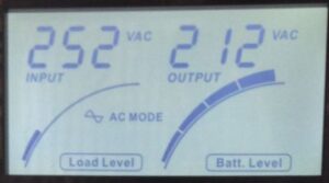
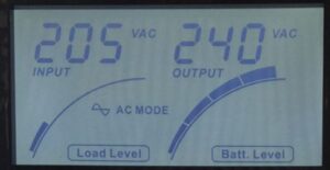
Here in this article I’m going to try and explain what one of our UPS does and for this I’m going to take the VIS2000B, apply varying voltage to it and observe the unit response. The VIS2000B is a good choice as the LCD display lets us know both input and output voltage so we don’t need to add any multimeters to the circuit. We’re going to modify the input voltage by means of a variable transformer, or a Variac. If you’re trying this at home don’t use a dimmer switch as these work in a different way.
Firstly we set the variac to nominal voltage, connect to the VIS2000B and switch it on. The display shows input voltage on the left at 230V and the output voltage on the right at 230V.
This is normal operation and so what comes in, goes out. What we will do now is increase the input voltage and observe.
As the voltage is increased the output voltage matches the input voltage until the buck trigger threshold is reached. This is set to be around the maximum voltage that the utility should provide which is 230 +10% = 253V.
In our case at 252V the unit enters buck mode and reduces the high input voltage to 212V. [Also note that on VIS2000B the AC Mode indicator blinks.]
The lower threshold of voltage supplied by the utility is open to some debate. It is 230V -10% = 207V in much of Europe and was supposed to be the same in the UK. However the implementation date of about 8 years ago has come and gone and so officially in the UK the voltage is still set to be 230V – 6% = 216V. However other standards for products that are CE marked generally require equipment to be able to operate across the full spectrum of nominal voltages, so the output is aimed to be regulated within the realm of the EU, so 230±10% or 207V to 253V.
Raising our test variac to as high as it could go saw the unit maintain in buck mode with the output voltage rising proportionally with the input. In buck mode the input voltage is reduced by a nominal 16% or so.
Raising the input voltage even higher results in the unit disabling buck mode and reverting to battery operation.
As we reduce the input voltage the buck will at some point be deactivated and the unit will return to normal. There must be some hysteresis built into this or the unit would “chatter” eg switch constantly in and out at the threshold voltage.
In our test with the unit output reaching 207V a further reduction in input voltage caused the unit to switch out of buck mode and back into normal mode.
With the mains input voltage reduced further the output voltage tracks the input voltage until the boost threshold is reached at around the 207V mark.
Here the mains input is raised by around 17-18% in order to maintain the voltage within the nominal range.
Further reductions in the input voltage will keep the unit in boost mode until the output voltage can no longer be maintained within tolerance and the unit will revert to battery operation.
Raising the voltage the unit comes out of battery mode, straight into boost which then is disabled when the input voltage reaches around 211V.
To summarise, a line interactive unit attempts to maintain the output voltage within regulated limits for as long as possible without dropping to battery power. This is an advantage of over offline UPS systems that will have no option but to drop to battery instead of providing regulation, which would resort in lost loads due to UPS switching off due to depleted battery, or diminished battery life if the unit is regularly switching in and out of battery mode. However, they do not provide tight output voltage control. To achieve this online double conversion UPS systems provide a constant fixed output voltage regardless of the input voltage level.
Additional Notes with regard to the VIS2000B
One of the drawbacks of UPS Systems is the need for them to prevent a build up of heat and so many are fitted with forced cooling fans. In our VIS2000B the unit fan activates when the unit is “active” that is, on battery but also when it is in buck or boost mode. Users may find their unit enters buck mode when their mains is around the 250V mark as this will be activated should the mains hit 252V even momentarily. Due to the hysteresis effects the fan will not be disabled until the lower threshold is reached which is around the 246V mark. If this occurs, briefly switching the unit onto battery power will clear the hysteresis effect.
Note that we can change the threshold somewhat to effectively shift the buck and boost points higher by around 10V or so. This prevents the unit entering a nuisance buck mode and also makes the minimum output voltage more within the current UK spec but this does mean that the unit will allow voltages of 260+V through, should these be encountered. This is a factory setting that the Power Inspired technicians would be happy to undertake for you if required.